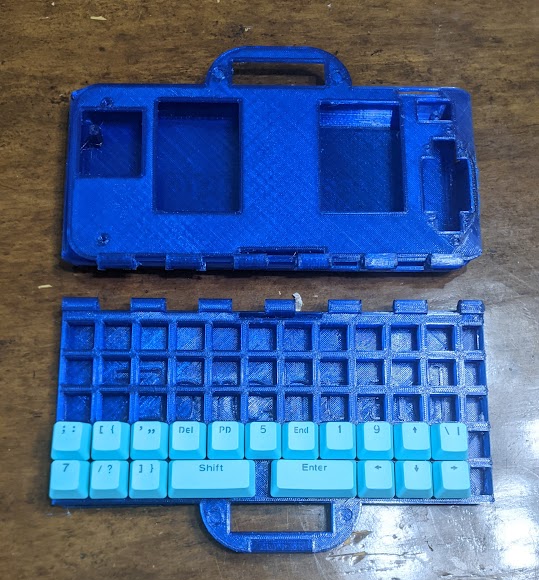
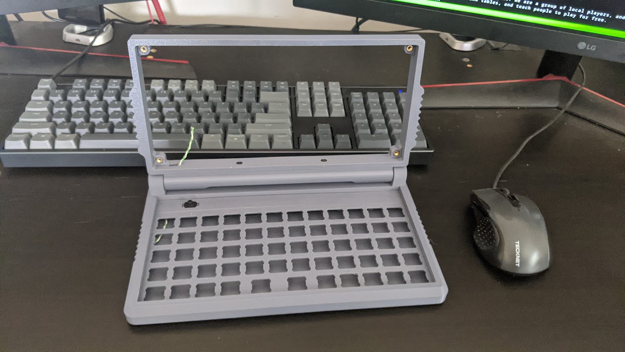
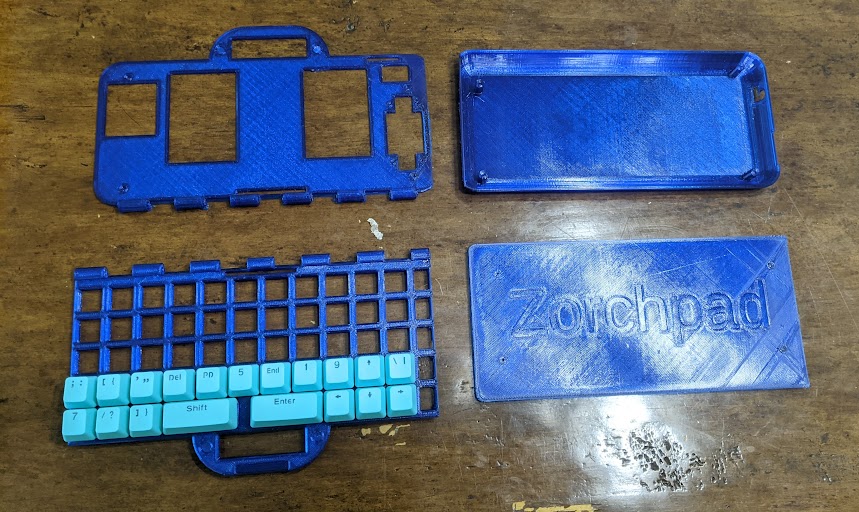
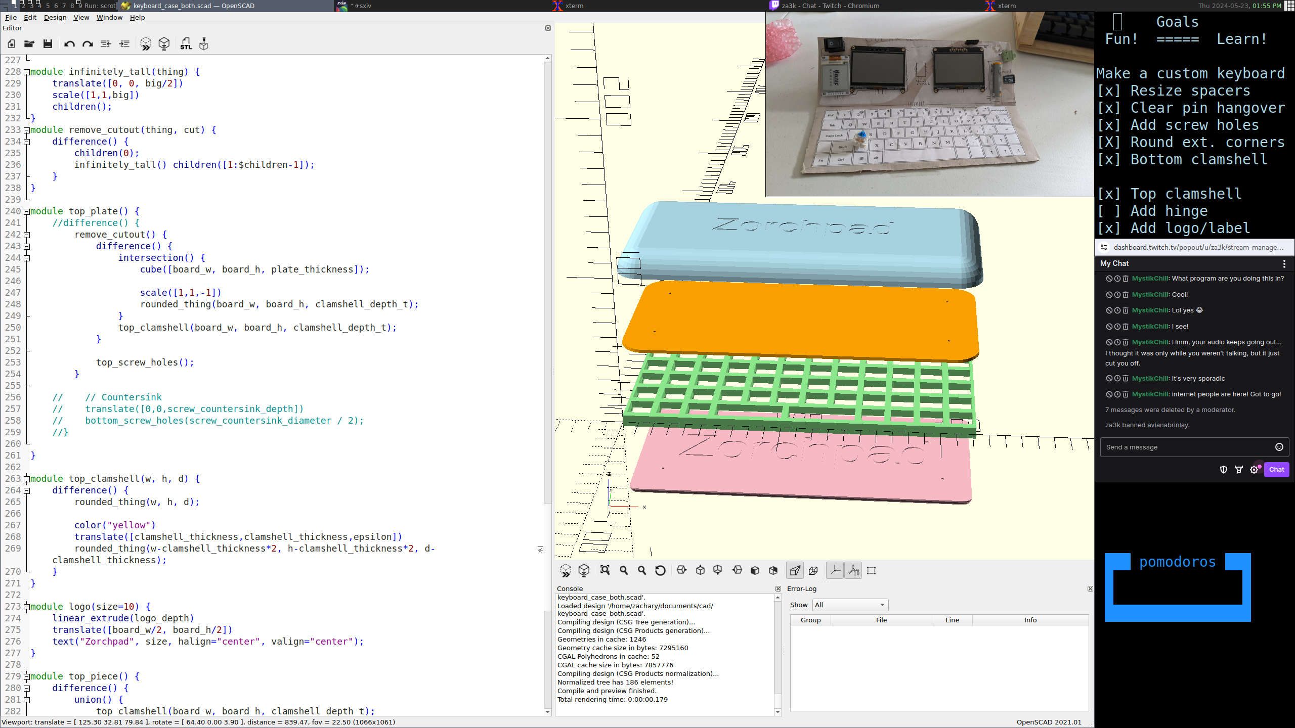
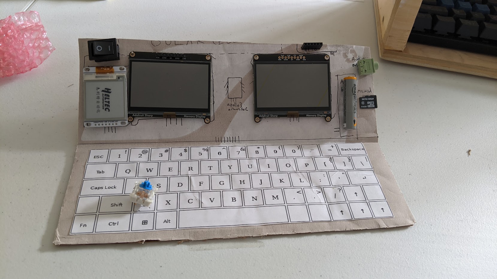
The Zorchpad is a low-power computer I'm working on. Standard keyboards unforunately need too much power, so I'm making my own.
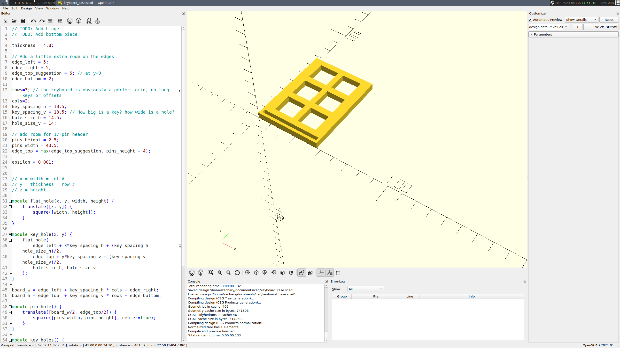
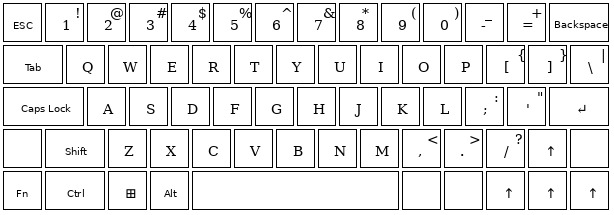
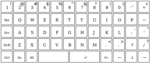
The keyboard layout I'm using has ~60 keys in a 12x5 grid.
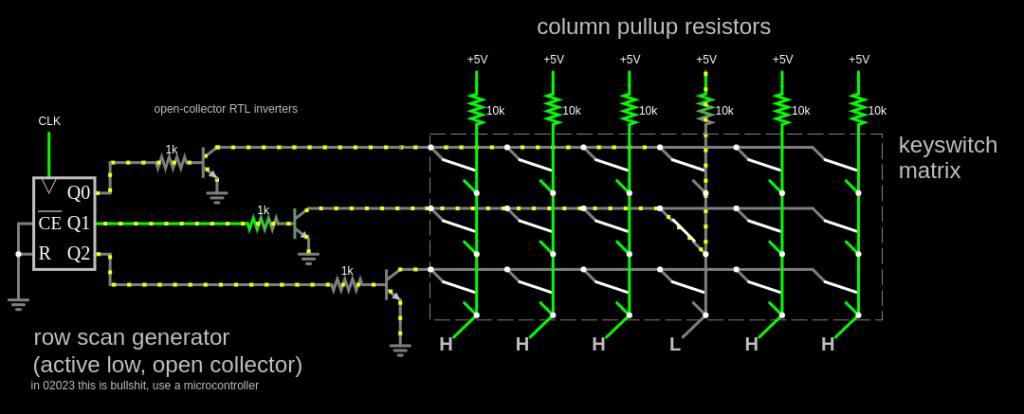
The standard way to wire a keyboard is to use a set of wires -- one for each row, one for each column. That's 12 + 5 wires = 17 wires. By driving one of 12 outputs low for a column, and checking each of 5 inputs, we can see which (if any) of the 5 keys in the column are being pressed. We then rapidly switch which of the 12 outputs is low, much faster than human speed, to see which of the 60 keys is pressed.
We'd like to support n-key-rollover, a term which means we can detect any number of keys being pressed at the same time. We don't really need lots of letter keys pressed at once, but this lets us not treat keys like Shift or Control specially. It doesn't cost much, and makes the hardware and software simpler.
Wiring things up the simplest way results in ghosting, a problem where if you press several keys at once, others can erroneously appear pressed as well. Installing a diode on each key solves the issue. Easy-peasy.
But we have a problem. My microcontroller doesn't have 17 free pins. So my plan is to instead use shift registers.
A serial-in, parallel-out shift register lets you send 8 bits, one at a time, and then a special pulse (the "latch"). This sets 8 different output channels.
A parallel-in, serial-out An input shift register lets you do the reverse--you set a "clock" pin to read from 8 input channels to an internal buffer, then read one of the stored bits at a time.
Using 1 SIPO and 1 PISO gives us 8 pins out and 8 pins in. It takes 3 pins per shift register. Some can be shared, so the total might be less than 6, but we have 6 free pins.
We need 12 outputs, not 8. How do we deal with that? One valid approach is to use 2 SIPO (or 2 PISO) shift registers. But I noticed that we only have 60 keys on the keyboard -- in theory 8 inputs x 8 outputs should be plenty. And in fact, we can rearrange things.
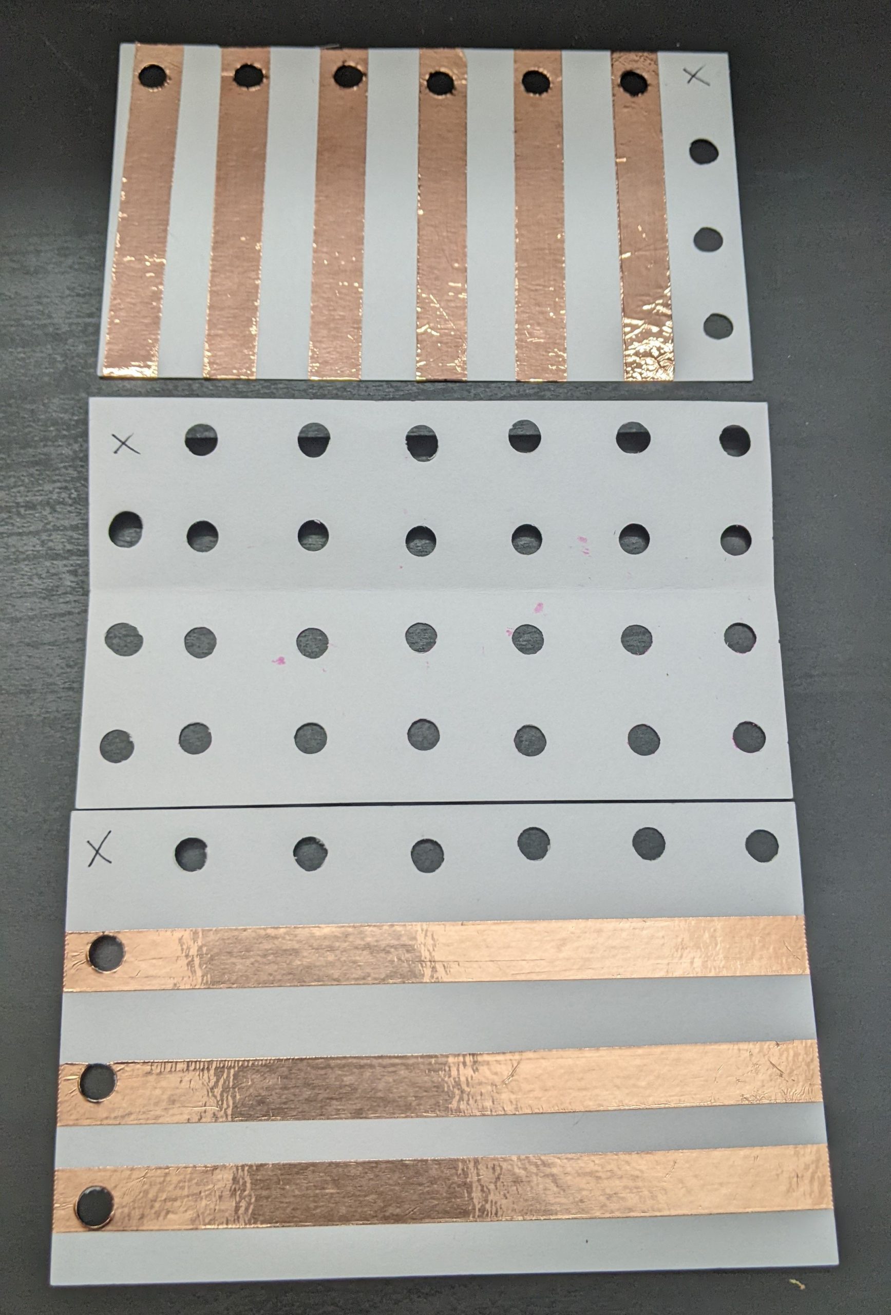
What if we take a 8x8 layout, which we know we can wire, and slice it up?
01234567 <-- column #

AAAAAAAA 0 <--- row #
AAAAAAAA 1
AAAAAAAA 2
AAAAAAAA 3
AAAAAAAA 4
BBBBCCCC 5
BBBBCCCC 6
BBBB---- 7
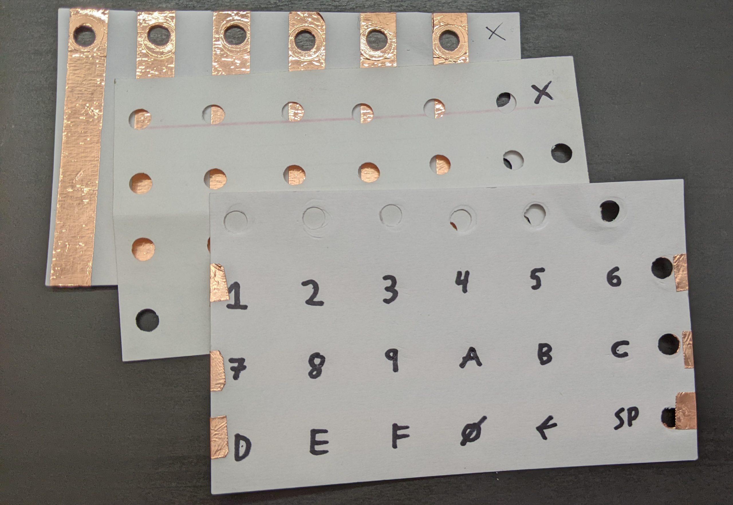
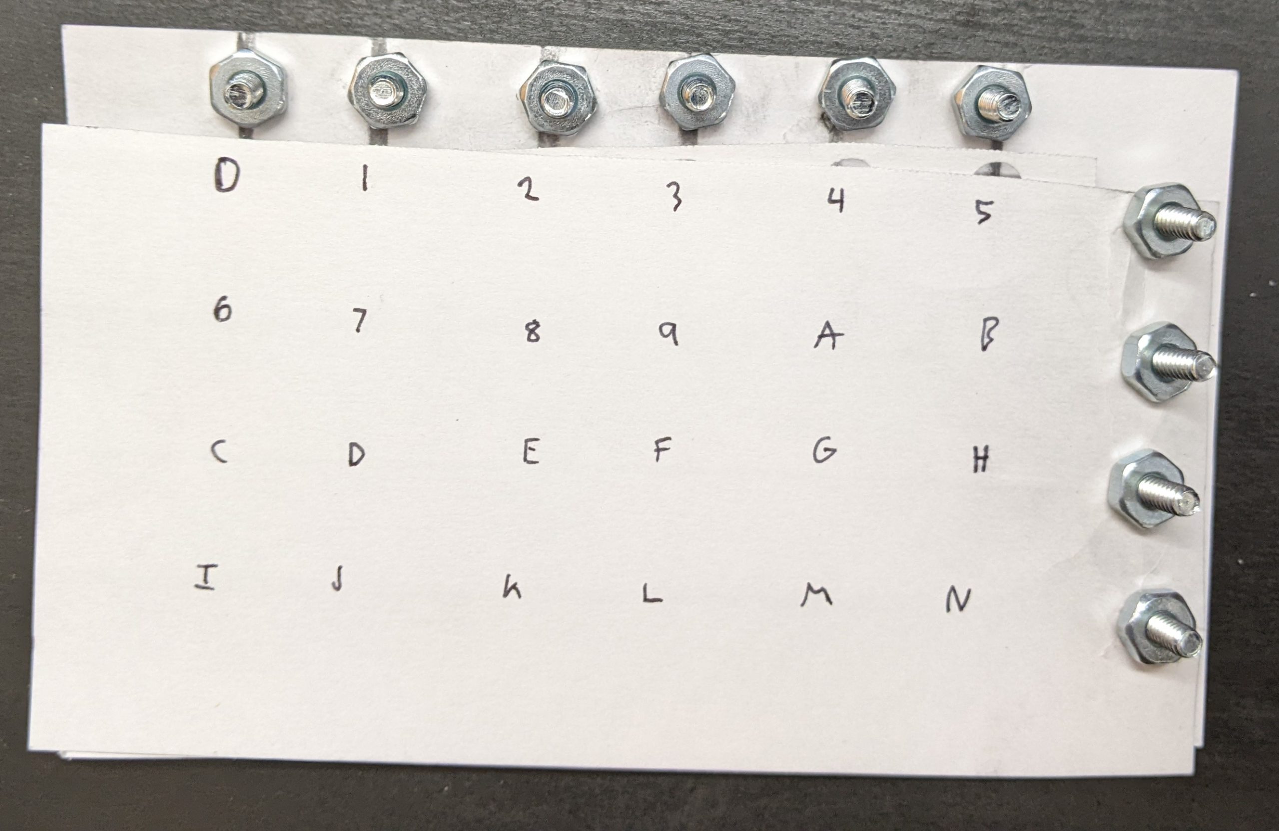
Re-arranging the pieces, we can make our 12x5 keyboard:
           01234567 0123 <- column #

row# --> 0 AAAAAAAA BBBB 5 <-- row #
         1 AAAAAAAA BBBB 6
         2 AAAAAAAA BBBB 7

         3 AAAAAAAA CCCC 5
         4 AAAAAAAA CCCC 6

                    4567 <- column #
(Thanks for splud of #electronics for this specific arrangement.)
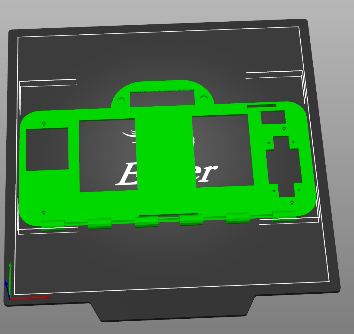
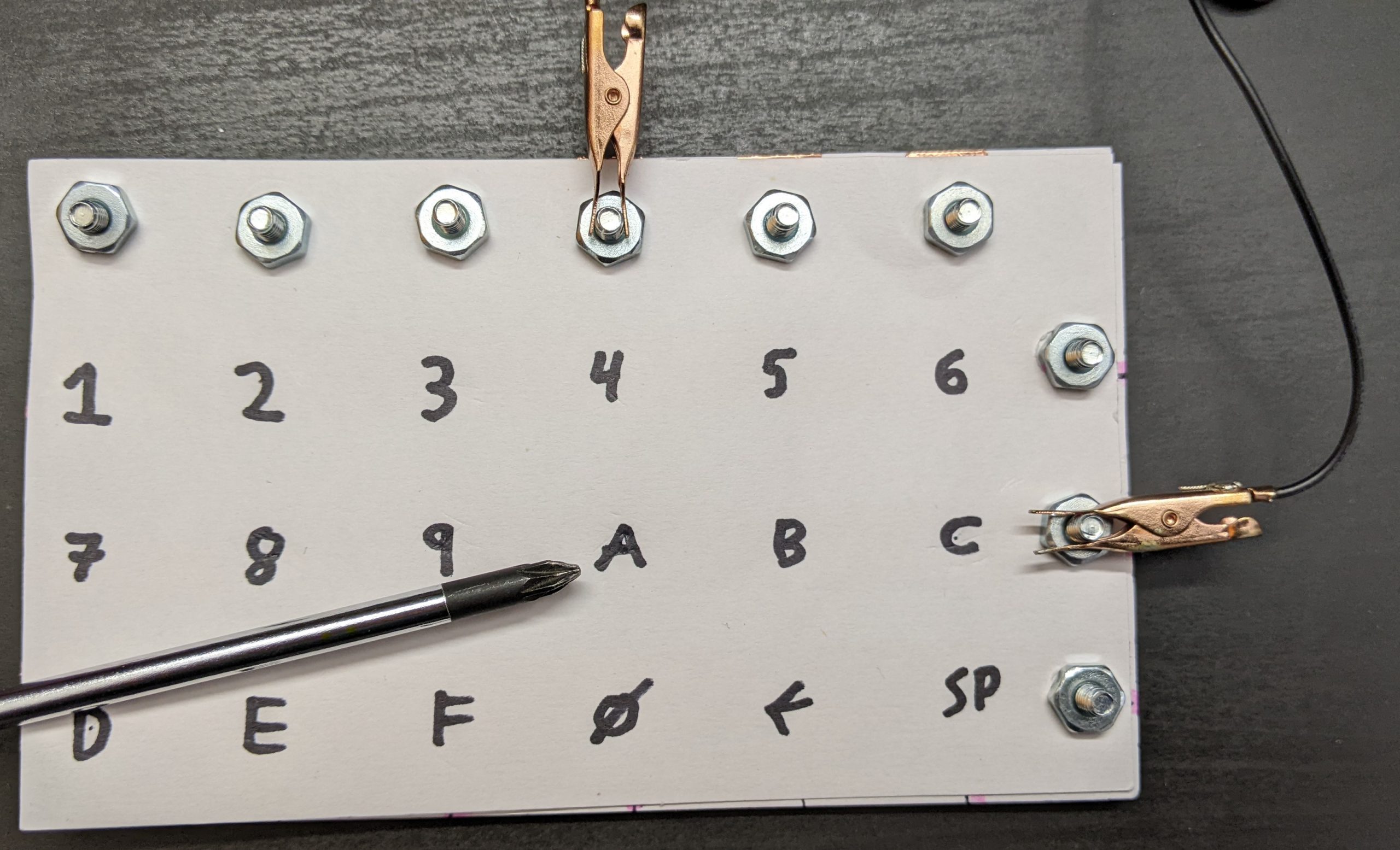
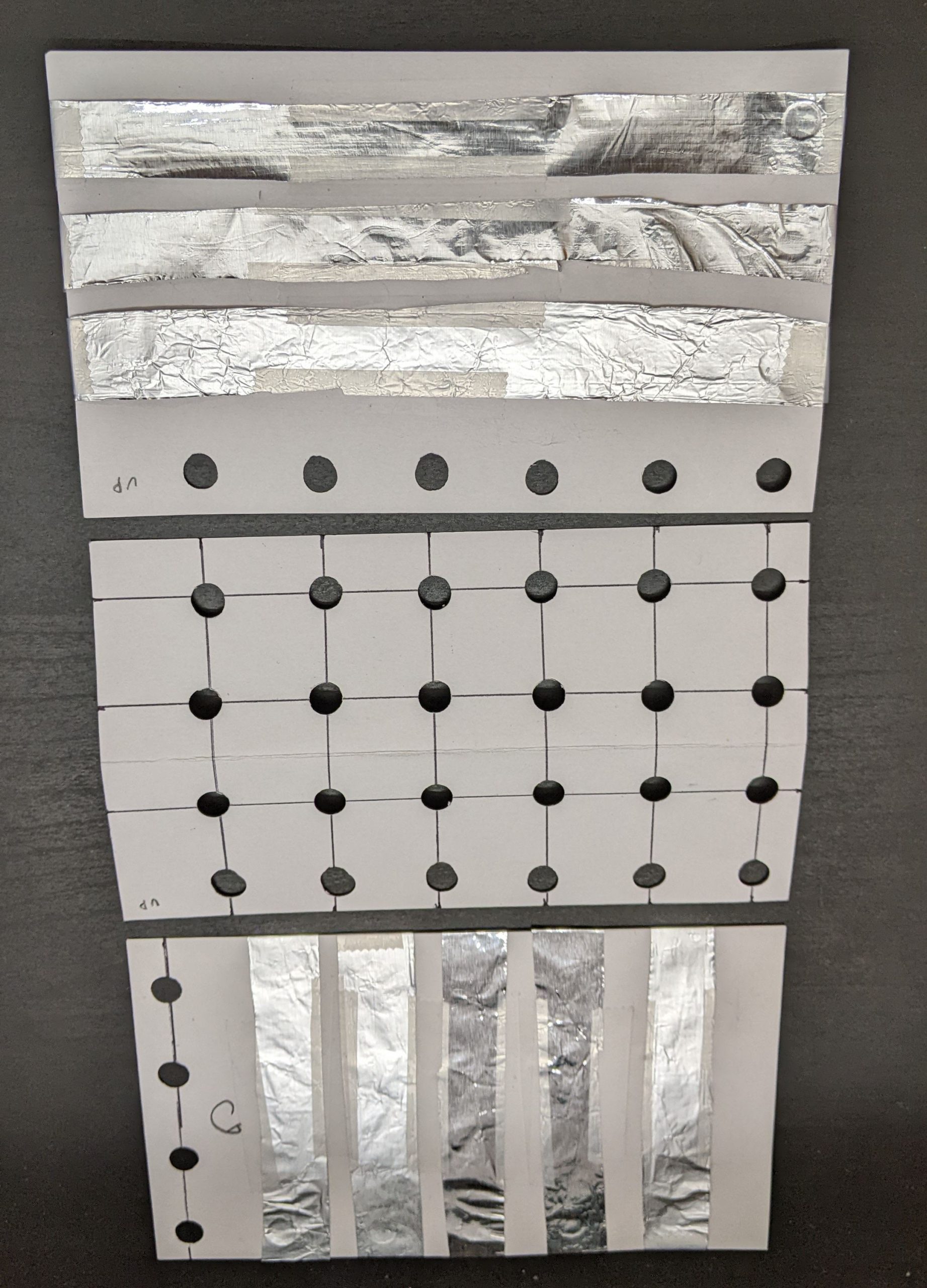
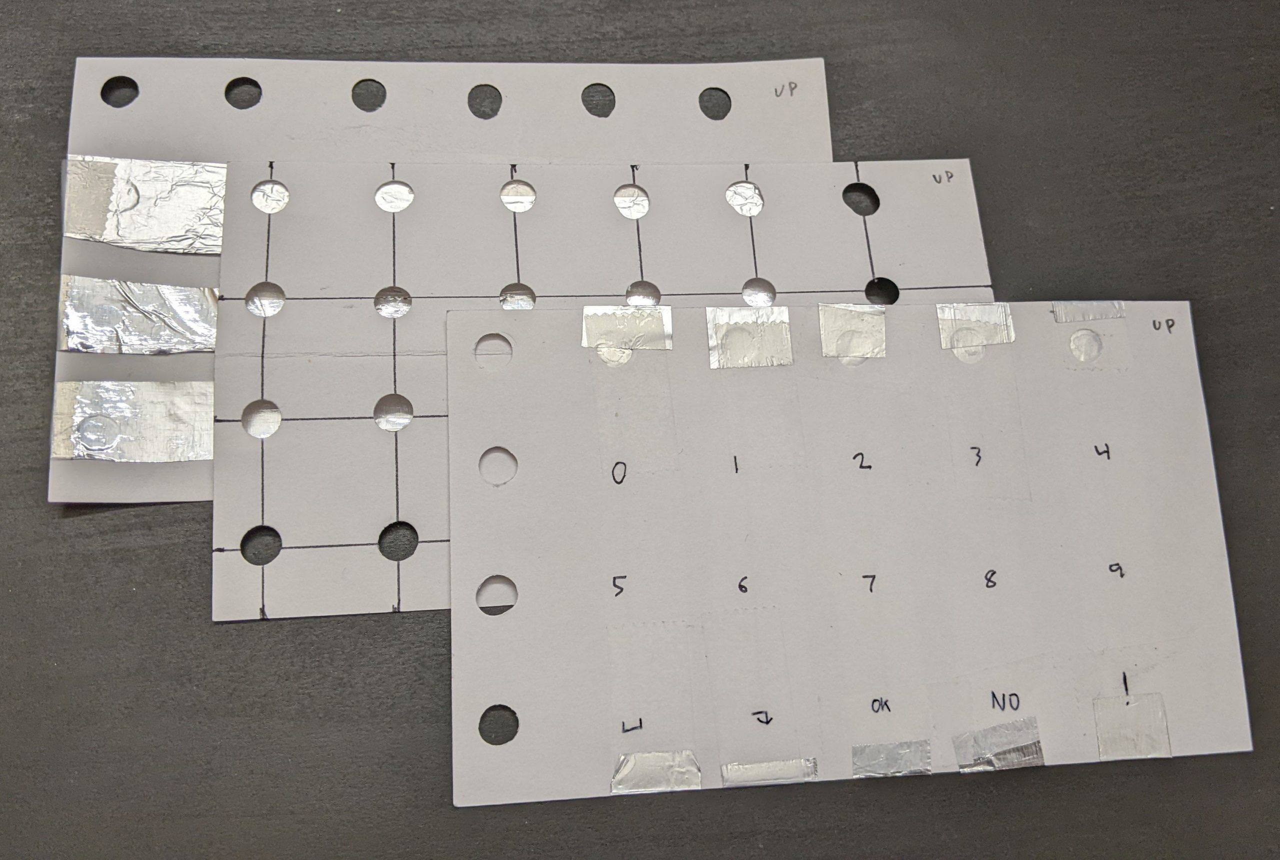
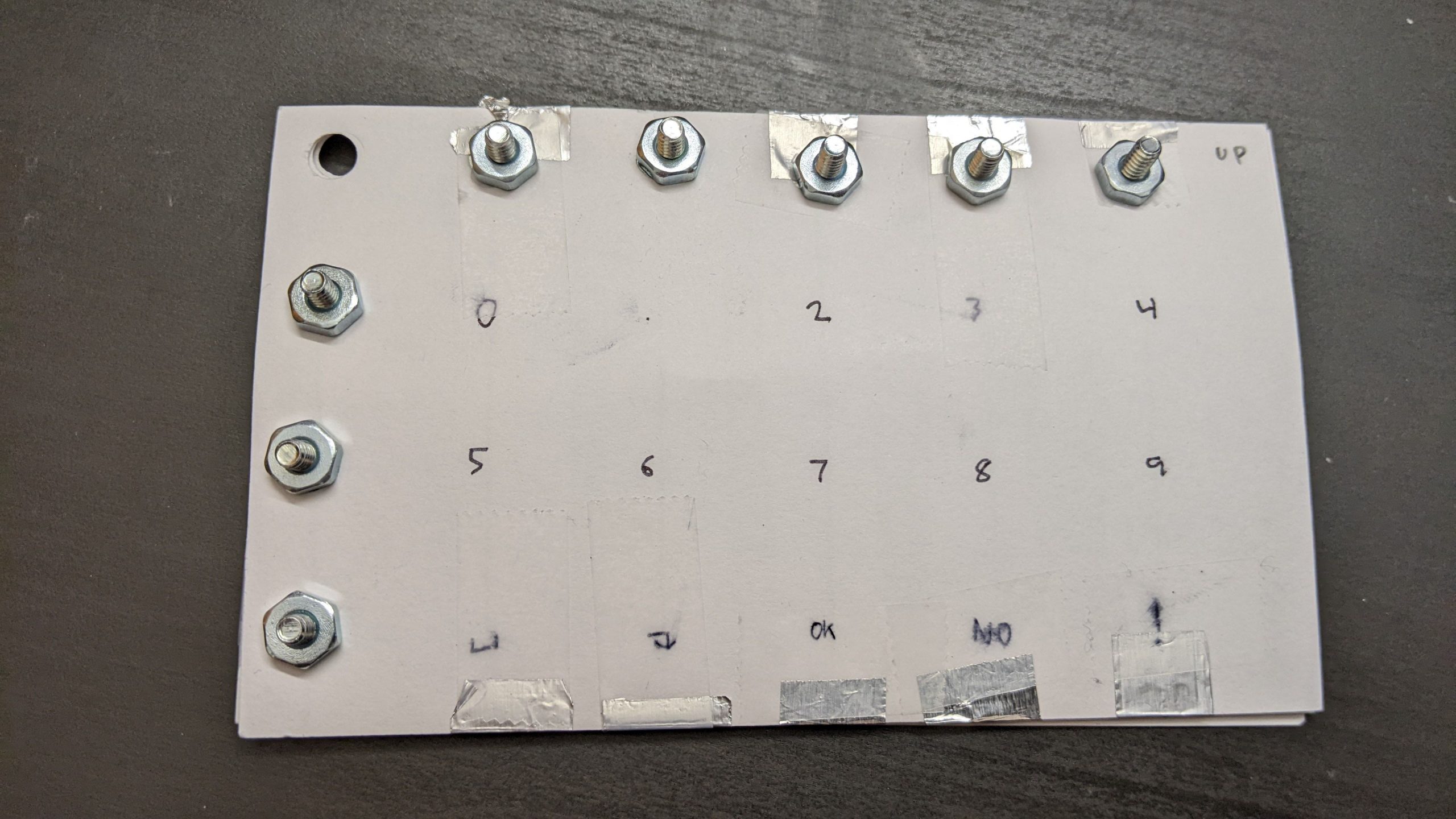
Looks great. All I need to do is hand-wire that layout onto a keyboard.
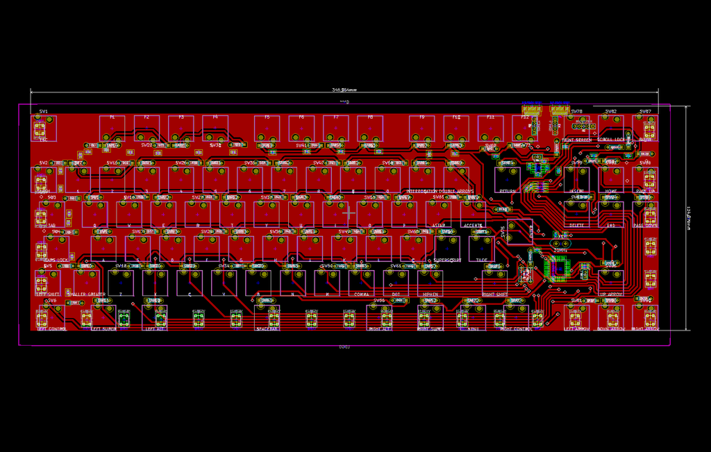
Okay... that looks hard. I really don't want to do the whole thing and realize I wired it wrong. Let's actually write out an entire schematic to make sure I do the right thing. We have a lot of complicated wiring and diode directions and so on.


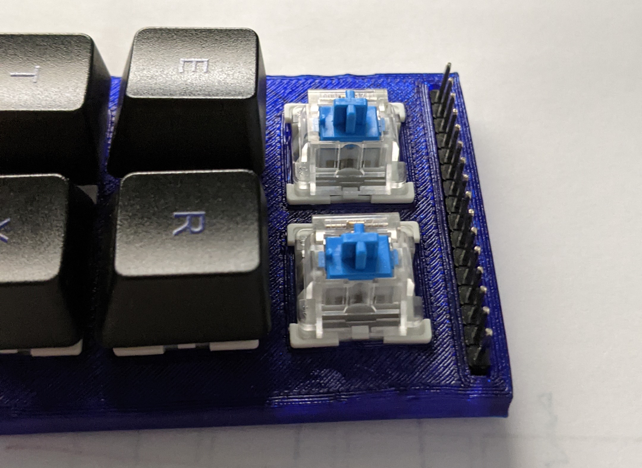
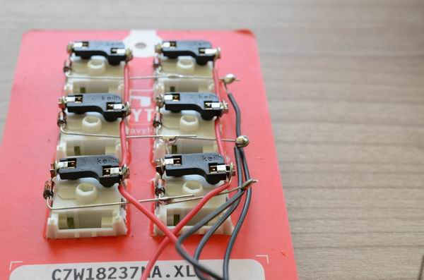
All right, I'm ready to assemble and solder. Wish me luck!