Zorchpad keyboard update

The Zorchpad needs a custom keyboard. Its power budget is only 1mW, and there’s just nothing available in that range. So, I need to make a custom keyboard. I started reading up on how to make your own–especially the electronics.

I don’t know how to make a PCB:

PCB from HacKeyboard

Or how to attach headers to the inside of an existing keyboard, which looks like this–:

Mapping the Innards of a Keyboard : 7 Steps (with Pictures) - Instructables

But I found a project called GOLEM with an excellent guide to making your own keyboard. Here is their wiring:

GOLEM Macropad
GOLEM Macropad

I can do that! They got me out of a major rut.


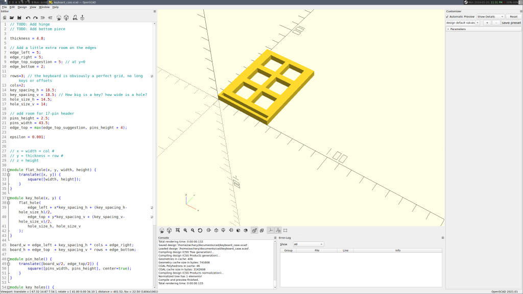
Their advice walks you through how to do a small keyboard in a cardboard plate. I did a few keys, gauged the effort, and decided to use my 3D printer. Cutting out 50-60 keys precisely by hand doesn’t sound easy. Worse, if you mess up, you have to start over. In plastic, I can’t mess up halfway, and the spacers to support the keyboard can be part of the print.

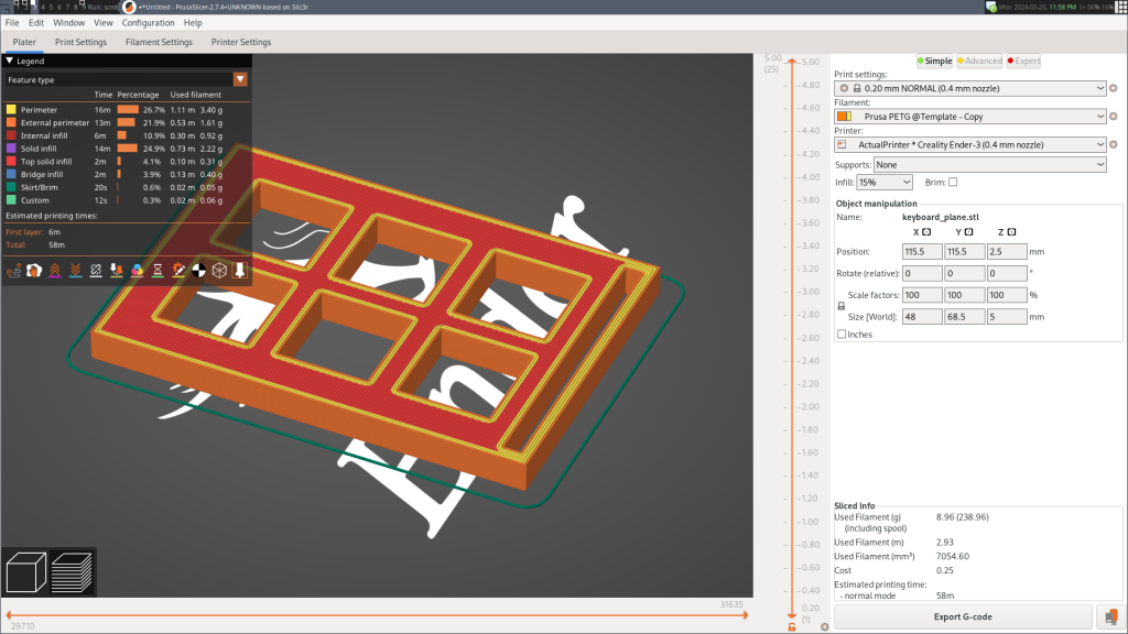
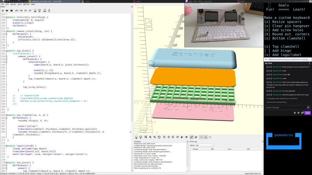
Above, I’m designing a “sampler” keyboard in CAD (OpenSCAD). I want to iron out problems in my process before I try a full-size keyboard. Below, Prusa-Slic3r is slicing the finished model for my 3D printer to print.

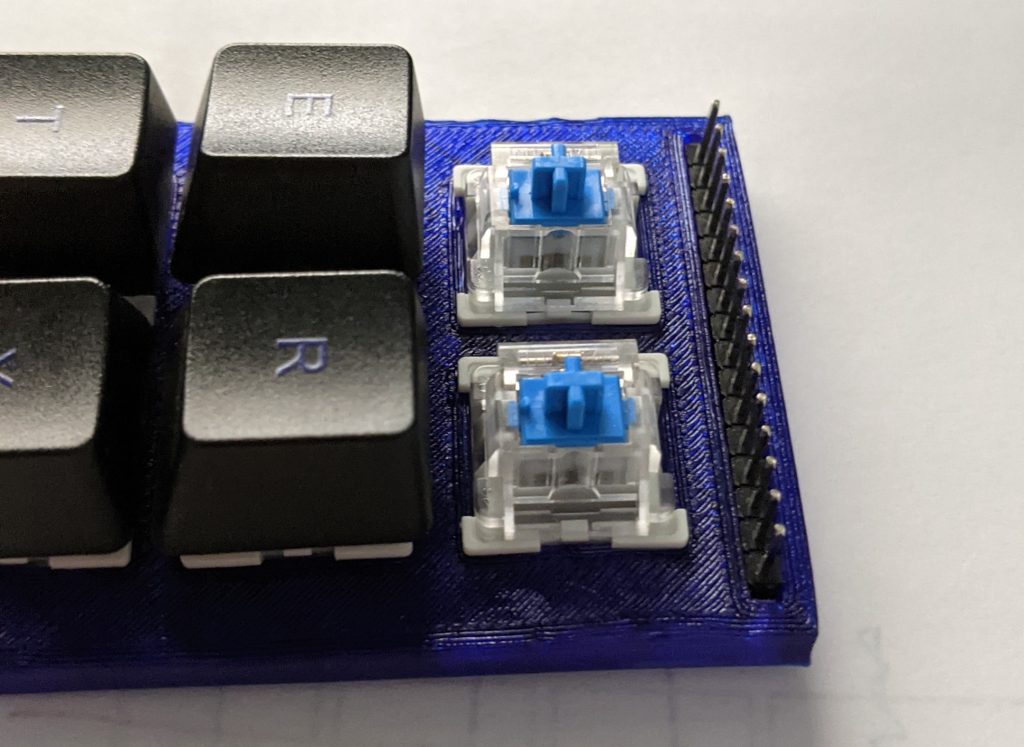
Here’s the finished sampler keyboard:

Currently I’m waiting on keycaps and switches ordered from China, and then I’ll put together my finished keyboard. But I have been making some progress in the meantime. Here’s the layout I’m going to try.

And I’ve started streaming some development of a case and keyboard on Twitch (Tue/Thu 12pm noon, EDT). Feel free to join! Anyone can watch, but you need an account to chat.

Tagged ,

Zorchpad Update: Keyboard

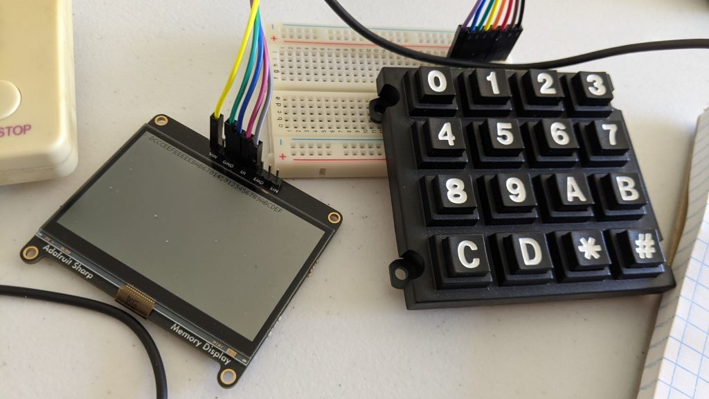
Another update on the zorchpad. We now have a working 16-button keyboard (sadly no QWERTY yet). Here you can see a simple typing program that shows what you type on screen.

As mentioned in a previous post, the reason we’re using a custom keyboard is to stay to low power usage–much lower than a standard keyboard.

So far we have:

Tagged ,

DIY keyboards (and how keyboards work)

I’ve been pondering simple input methods for microcontrollers. One obvious idea is, a keyboard! But for some reason, my USB keyboards use a staggering amount of power compared to my microcontrollers–1W of power for my mechanical keyboards, maybe 0.1W for the regular ones.

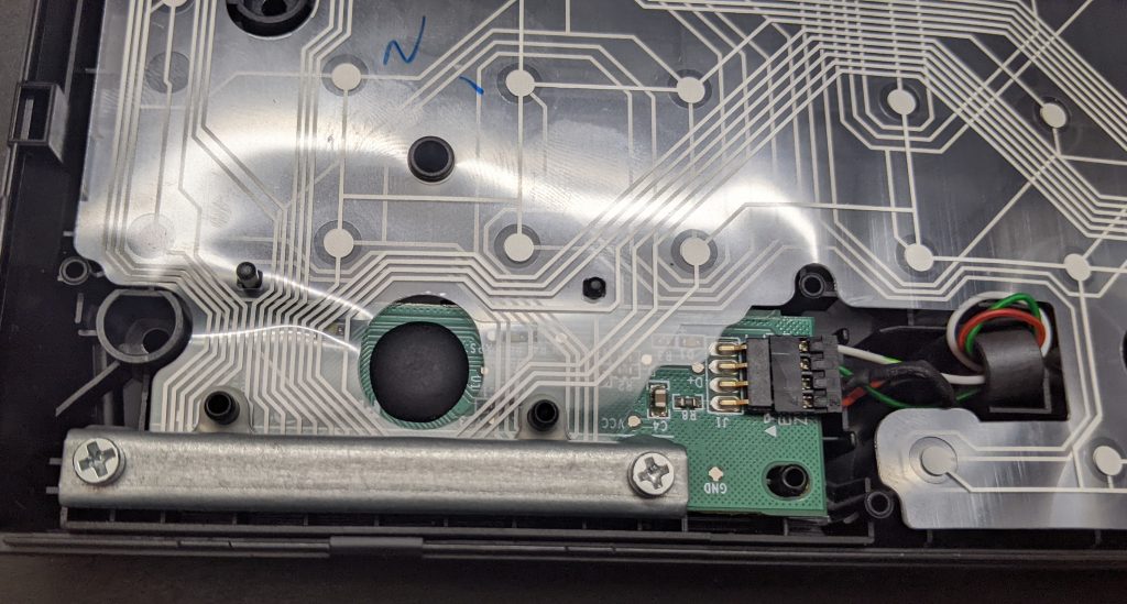
Let’s look inside a commercial keyboard, and see if we can hook up to it:

a photograph of the interior of a commercial keyboard. there is a PCB, with two layers of flexible conductor on top, all clamped down

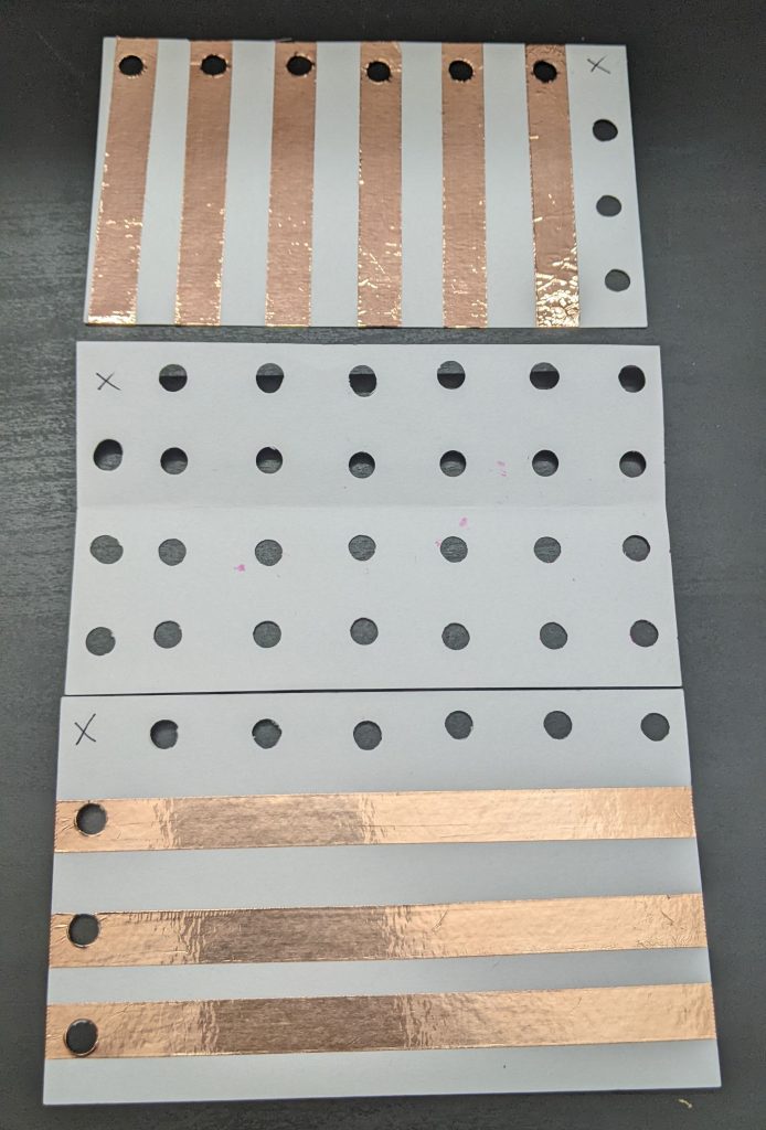
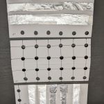
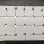
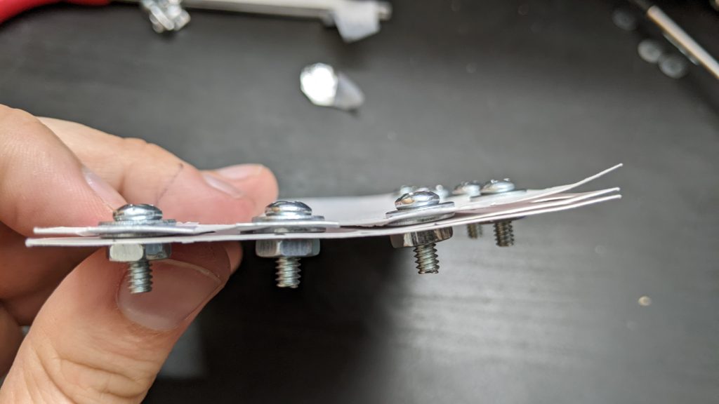
Yikes. What’s going on? Well, let’s make our own little keyboard, and explore what’s going on. We’ll build it in three layers, or “index cards”:

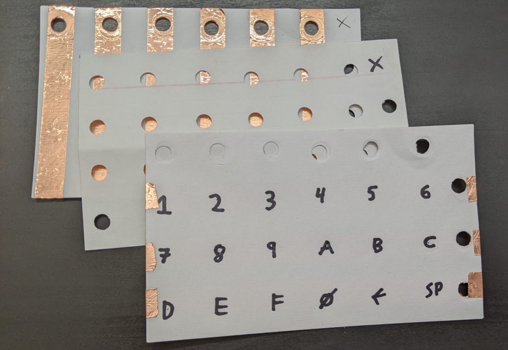
The bottom layer has 6 vertical stripes. The top layer has 3 horizontal stripes. Each place they cross will be a “key” you can press.

In between them, we add a spacer layer (punched holes) so they keys are “up” by default, and you have to press them to make them connect.

This picture might help explain how they will go together:

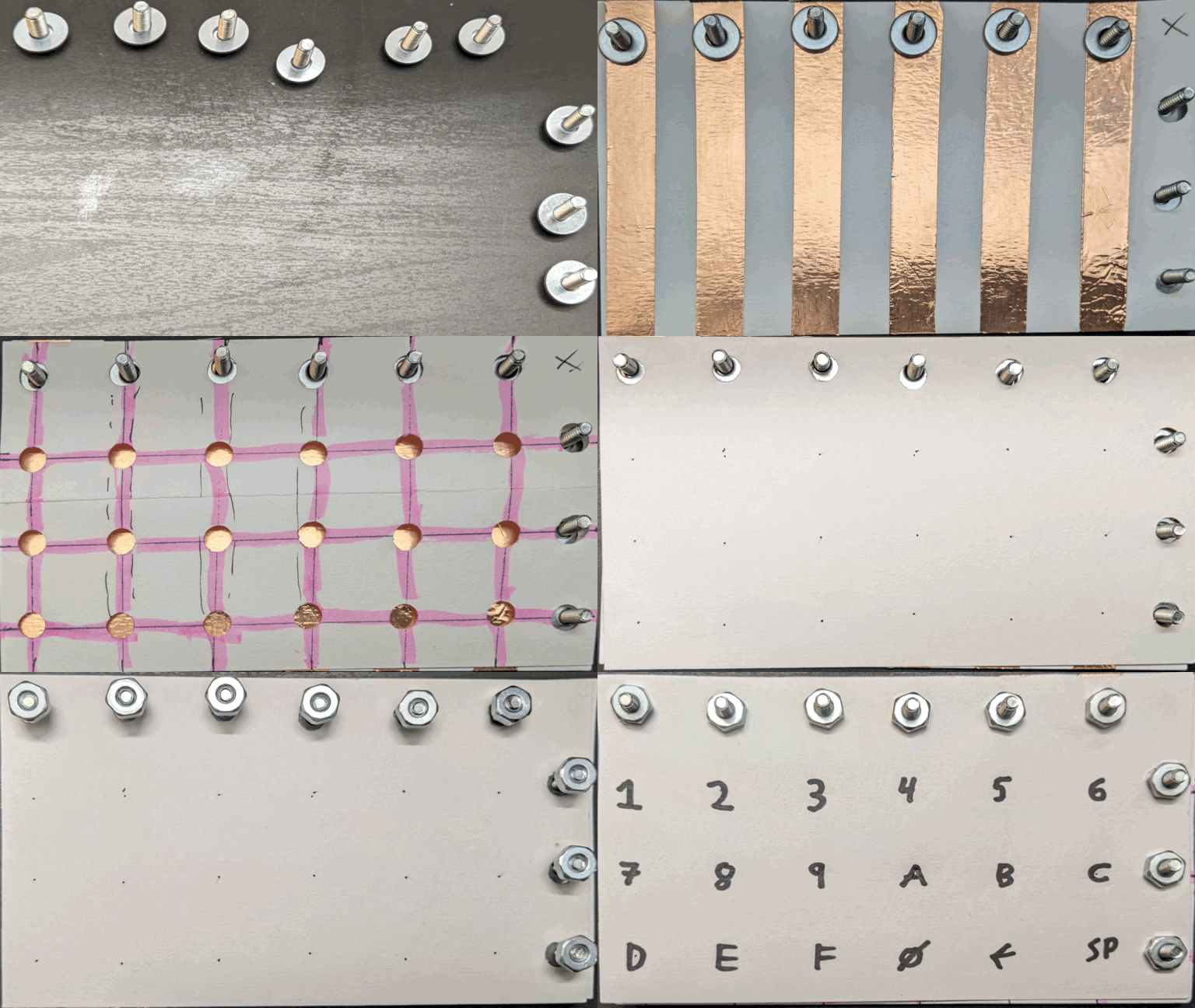
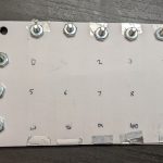
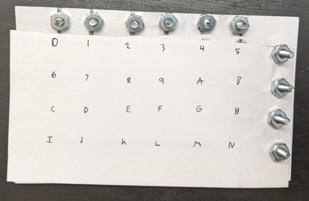
Now we assemble:

The final keyboard has 6 x 3 = 18 “keys”. We write the hex digits plus a couple extra keys with marker.

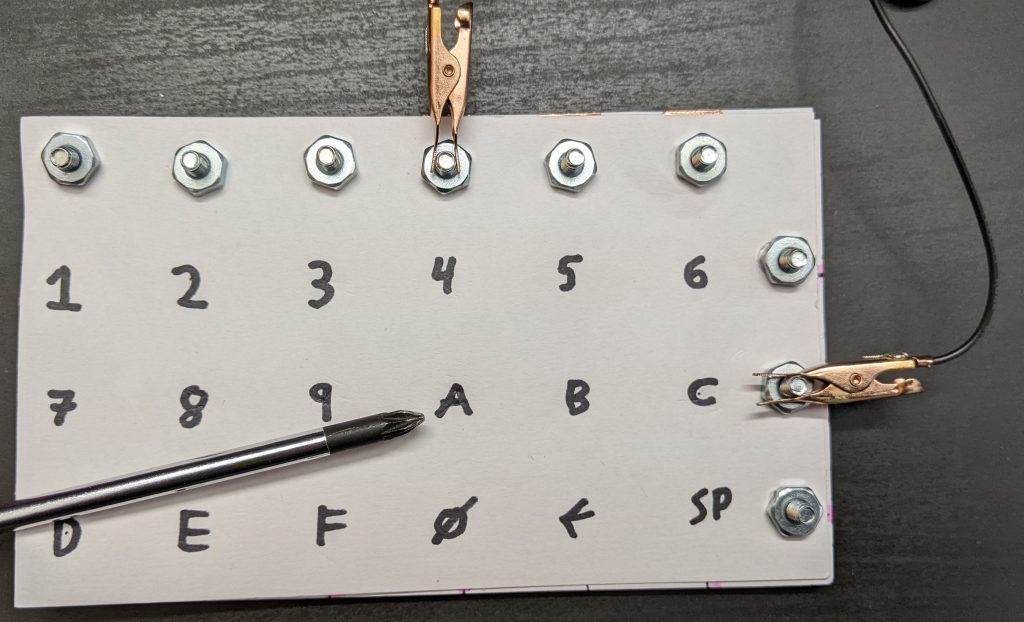
If I attach alligator clips to the second horizontal screw terminal, and fourth vertical screw terminals, and wire a battery and buzzer with the terminals, I get a connection beep only when I press the key “A”:

Two terminals with alligator clips attached to row and column terminals, and a screwdriver pointing at the "A" key addressed.

In a real computer, we obviously can’t just move alligator clips around. Instead, we attach wires to all 9 posts–three outputs wires for the horizontal lines, and six inputs for the vertical lines. We output a signal on the first horizontal line, and see if we can read it from any of the six vertical lines inputs. Then we output a signal on the second horizontal line, and see if we can read it, and so on for the third. Assuming only one key is pressed (or none), we can identify the key. This “scanning” process could be done thousands of times a second, rapidly enough that it can’t miss our slowpoke human fingers.

Click to view interactive schematic (credit: Kragen)

And this is how most keyboards work. There are some special keys–Shift, Ctrl, Alt, etc might be on their very own line, since we want to detect key combos. And better keyboards can detect multiple keys being pressed at once (N-key rollover), which I think they do by having a completely separate wire to each key which multiple people tell me they do with a diode next to each key.

For the above project, I used:

  • Three index cards
  • A hole punch
  • Scissors
  • A ruler
  • A pen (NOT a pencil, since graphite is conductive)
  • 9 screws, 9 nuts, and 18 washes. I selected #6 American Wire Gauge, which is about 4mm thickness
  • Copper tape

Did this work perfectly? Definitely not.

  • On some keyboards I’ve made, you have to press quite hard.
  • My multimeter takes a while to register a press. I think a microcontroller would be better.
  • You have to attach the terminals carefully. I think what’s going on is that you can actually put the screw exactly through the center of the washer which is actually making contact with the strips, so that only the washer is attached, and the screw doesn’t rub against the washer.
  • It’s of course fairly easy to mis-align anything. This is pretty easy to fix with care. I used the “spacer” grid to draw the centerpoint of the printed letters.
  • The screw heads are a bit thick, so it’s hard to press the keys in the column/row next to the screws. A piece of backing cardboard might fix this.

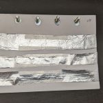
This was my third attempt. Here’s the second, using aluminium foil. It worked at least as well, maybe better, but it was harder to make. I just taped the foil down, taking care not to cover the contact points. I am told the aluminium will gradually oxidize, making it non-conductive.

And here’s one using graphite from drawing hard with a #2 pencil.. Graphite, it turns out, works terribly, and I couldn’t read a signal halfway down the index card. Despite what people have told me, I’m not yet convinced you can make a conductive wire out of it.

Tagged , ,

Introducing the Zorchpad (+ display demo)

A friend of mine, Kragen Javier Sitaker has been designing something he calls the zorzpad (see link below). I can never remember the name, so as a joke my version became the “zorch pad”. We live on opposite sides of the globe, but we’ve picked up the same or similar hardware, and have been having fun developing the hardware and software together.

The basic idea of the Zorchpad is to have one computer, indefinitely. It should keep working until you die. That means no battery that runs out, and no parts that go bad (and of course, no requirements to “phone home” for the latest update via wifi!). This is not your standard computer, and we’ve been trying a lot of experimental things. One of the main requirements is that everything be very low-power. He picked out the excellent apollo3 processor, which theoretically runs at around 1mW. In general, the zorchpad is made of closed-source hardware.

Since I’ve realized this will be a long project, I’m going to post it piece-by-piece as I make progress. Below is a demo of the display.

The graphics demo shows, in order:

  • a title screen
  • a flashing screen (to show graphics-mode framerate)
  • a demo of font rendering. we’re using the fixed-width font tamsyn.
  • a munching squares animation
  • a demo of how fast “text-mode” updates would be

We’re using a memory-in-pixel LCD. The only manufacturer is Sharp LCD. You have have seen these before in things like the Pebble watch–they’ve very low-power except when you’re updating. This particular screen is quite tiny–240x400px display (which is fine with me), but only 1.39×2.31 inches (35x59mm). The only bigger screen available in this technology is 67x89mm, a bit lower resolution, and out of stock. As soon as it’s in stock I plan to switch to it.

According to the datasheet, the screen consumes 0.05-0.25mW without an update, and perhaps 0.175-0.35mW updating once per second. We haven’t yet measured the real power consumption for any of the components.

The most obvious alternative is e-ink. E-ink has a muuuch slower refresh rate (maybe 1Hz if you hack it), and uses no power when not updating. Unfortunately it uses orders of magnitude more power for an update. Also, you can get much larger e-ink screens. The final zorchpad might have one, both or something else entirely! We’re in an experimentation phase.

Datasheets, a bill of materials, and all source code can be found in my zorchpad repo. Also check out Kragen’s zorzpad repo.

Tagged , , ,

Making a hardware random number generator

If you want a really good source of random numbers, you should get a hardware generator. But there’s not a lot of great options out there, and most people looking into this get (understandably) paranoid about backdoors. But, there’s a nice trick: if you combine multiple random sources together with xor, it doesn’t matter if one is backdoored, as long as they aren’t all backdoored. There are some exceptions–if the backdoor is actively looking at the output, it can still break your system. But as long as you’re just generating some random pads, instead of making a kernel entropy pool, you’re fine with this trick.

So! We just need a bunch of sources of randomness. Here’s the options I’ve tried:

  • /dev/urandom (40,000KB/s) – this is nearly a pseudo-random number generator, so it’s not that good. But it’s good to throw in just in case. [Learn about /dev/random vs /dev/urandom if you haven’t. Then unlearn it again.]
  • random-stream (1,000 KB/s), an implementation of the merenne twister pseudo-random-number generator. A worse version of /dev/urandom, use that unless you don’t trust the Linux kernel for some reason.
  • infnoise (20-23 KB/s), a USB hardware random number generator. Optionally whitens using keccak. Mine is unfortunately broken (probably?) and outputs “USB read error” after a while
  • OneRNG (55 KiB/s), a USB hardware random number generator. I use a custom script which outputs raw data instead of the provided scripts (although they look totally innocuous, do recommend
  • /dev/hwrng (123 KB/s), which accesses the hardware random number generator built into the raspberry pi. this device is provided by the raspbian package rng-tools. I learned about this option here
  • rdrand-gen (5,800 KB/s), a command-line tool to output random numbers from the Intel hardware generator instruction, RDRAND.

At the end, you can use my xor program to combine the streams/files. Make sure to use limit the output size if using files–by default it does not stop outputting data until EVERY file ends. The speed of the combined stream is at most going to be the slowest component (plus a little slowdown to xor everything). Here’s my final command line:

#!/bin/bash
# Fill up the folder with 1 GB one-time pads. Requires 'rng-tools' and a raspberry pi. Run as sudo to access /dev/hwrng.
while true; do
  sh onerng.sh | dd bs=1K count=1000000 of=tmp-onerng.pad 2>/dev/null
  infnoise --raw | dd bs=1K count=1000000 of=tmp-infnoise.pad 2>/dev/null
  xor tmp-onerng.pad tmp-infnoise.pad /dev/urandom /dev/hwrng | dd bs=1K count=1000000 of=/home/pi/pads/1GB-`\date +%Y-%m-%d-%H%M%S`.pad 2>/dev/null;
done

Great, now you have a good one-time-pad and can join ok-mixnet 🙂

P.S. If you really know what you’re doing and like shooting yourself in the foot, you could try combining and whitening entropy sources with a randomness sponge like keccak instead.

Tagged , ,

DIY Hard drive carrying case

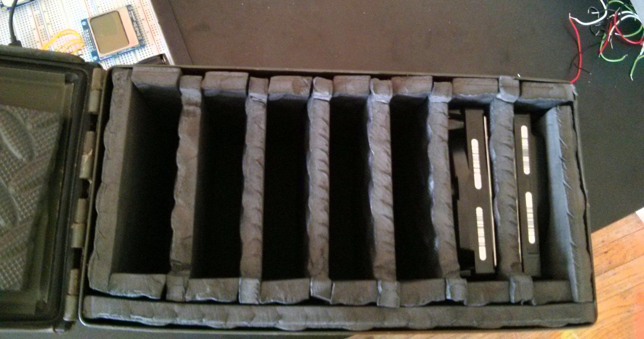
Today’s project was a hard drive carrying case. I wanted something to securely store hard drives. When I looked around on ebay and amazon, I saw some nice cases and some crappy plastic molded ones. Even the terrible ones were at least $50, so I made my own.

HDD Carrying Case Exerior

I bought a used ammo case at the rather excellent local army surplus store. Then I padded all sides. I had spare EVA foam “puzzle piece” style mats from a gym setup lying around. I cut out the pieces with scissors. That’s it.  I was expecting more steps, but nothing needed glued in place. I was planning on adding inserts for the empty slots, but it seems secure enough. If you’re making one, you could also glue the top onto the lid, so you don’t have to take it out manually.

HDD Case Interior
Tagged , , , , , , ,

Getting the Adafruit Pro Trinket 3.3V to work in Arch Linux

I’m on Linux, and here’s what I did to get the Adafruit Pro Trinket (3.3V version) to work. I think most of this should work for other Adafruit boards as well. I’m on Arch Linux, but other distros will be similar, just find the right paths for everything. Your version of udev may vary on older distros especially.

  1. Install the Arduino IDE. If you want to install the adafruit version, be my guest. It should work out of the box, minus the udev rule below. I have multiple microprocessors I want to support, so this wasn’t an option for me.
  2. Copy the hardware profiles to your Arduino install. pacman -Ql arduino shows me that I should be installing to /usr/share/aduino.  You can find the files you need at their source (copy the entire folder) or the same thing is packaged inside of the IDE installs.

    cp adafruit-git /usr/share/arduino/adafruit
    
  3. Re-configure “ATtiny85” to work with avrdude. On arch, pacman -Ql arduino | grep "avrdude.conf says I should edit /usr/share/arduino/hardware/tools/avr/etc/avrdude.conf. Paste this revised “t85” section into avrdude.conf (credit to the author)

  4. Install a udev rule so you can program the Trinket Pro as yourself (and not as root).

    # /etc/udev/rules.d/adafruit-usbtiny.rules
    SUBSYSTEM=="usb", ATTR{product}=="USBtiny", ATTR{idProduct}=="0c9f", ATTRS{idVendor}=="1781", MODE="0660", GROUP="arduino"
    
  5. Add yourself as an arduino group user so you can program the device with usermod -G arduino -a <username>. Reload the udev rules and log in again to refresh the groups you’re in. Close and re-open the Arduino IDE if you have it open to refresh the hardware rules.

  6. You should be good to go! If you’re having trouble, start by making sure you can see the correct hardware, and that avrdude can recognize and program your device with simple test programs from the command link. The source links have some good specific suggestions.

Sources:
http://www.bacspc.com/2015/07/28/arch-linux-and-trinket/
http://andijcr.github.io/blog/2014/07/31/notes-on-trinket-on-ubuntu-14.04/

Tagged , , , , , ,