Hack-a-Day, Day 30: LED Fireplace

Having prepped my ESP-32, I decided to make an LED fireplace today.

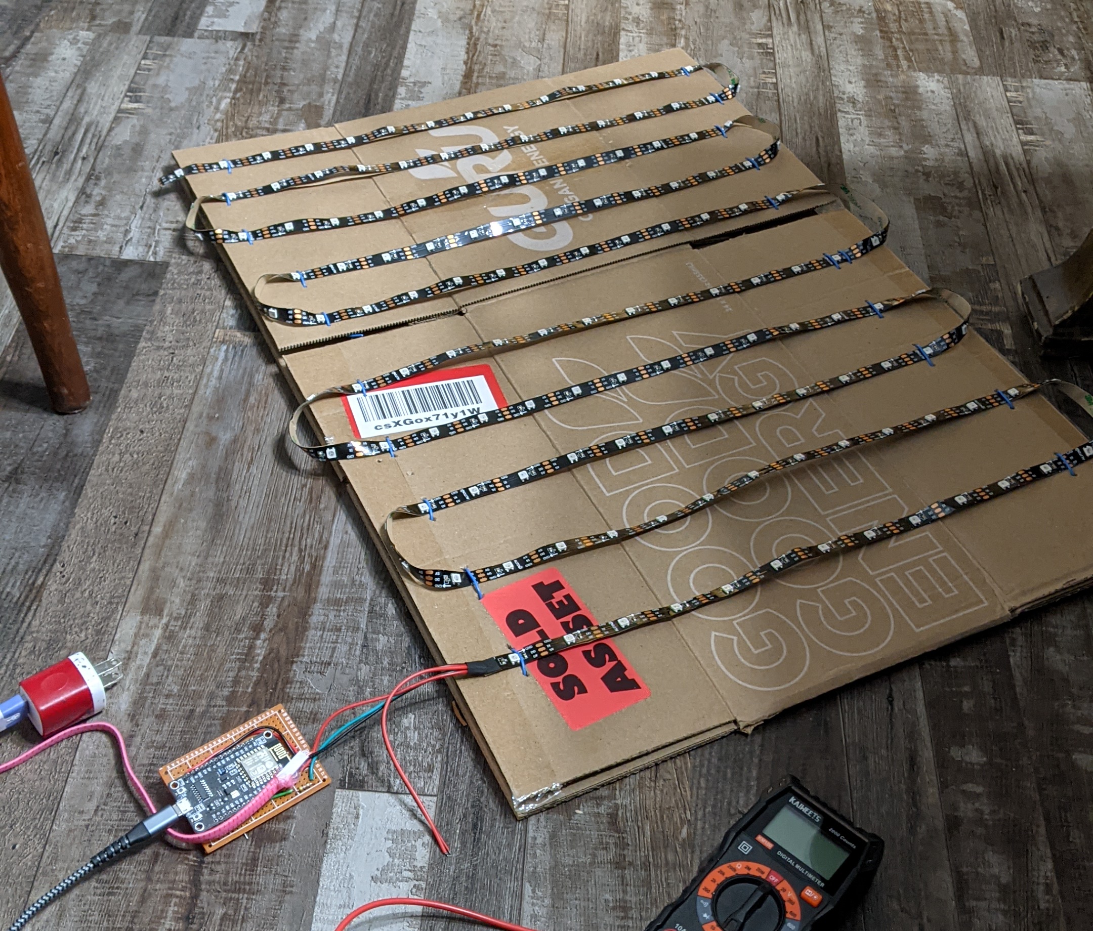
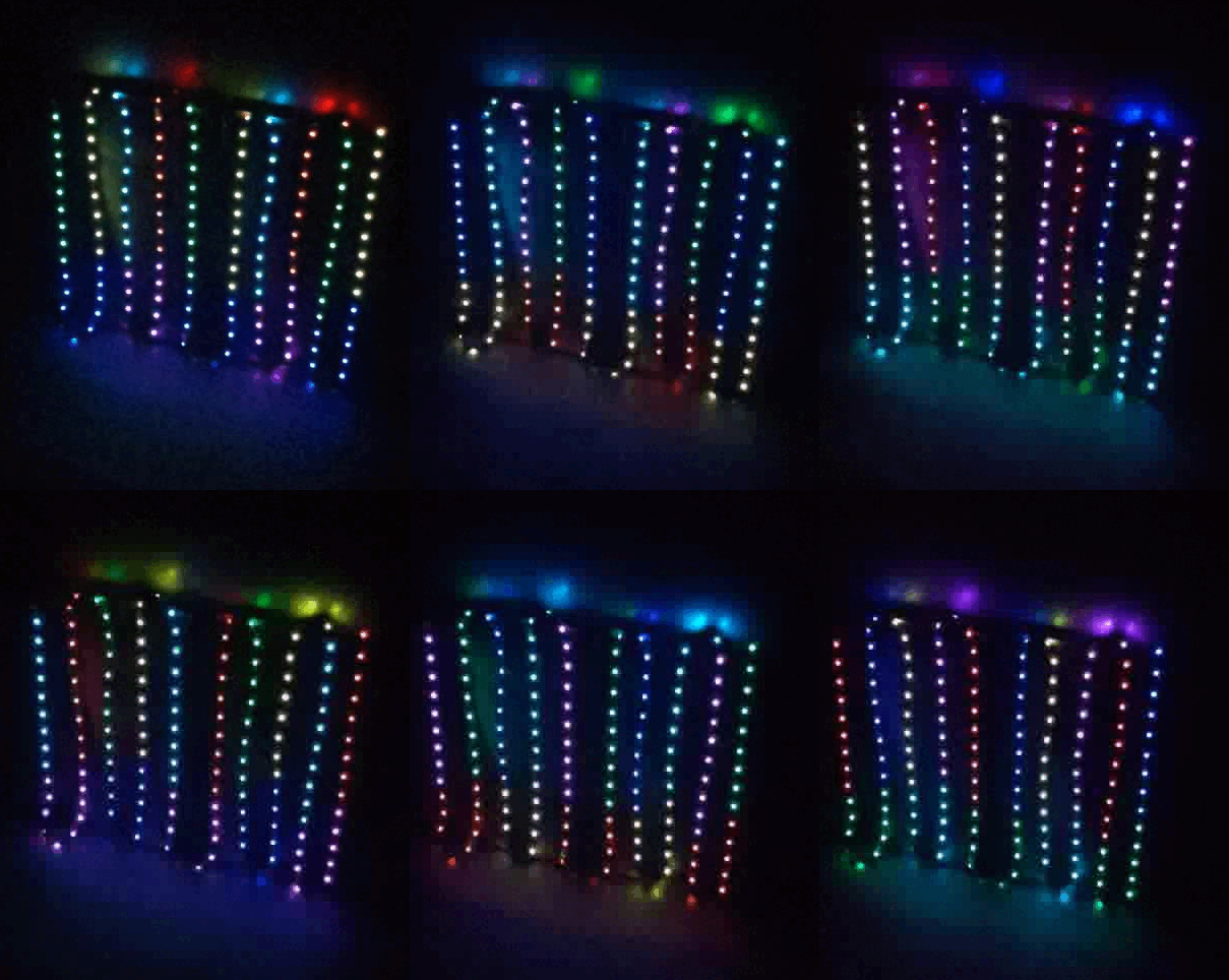
The plan was to put an LED strip on a piece of cardboard, and have slowly shifting red, orange, and yellow lights going up and down, somewhat like a music visualizer. I knew the bare LEDs wouldn't look good, so the plan was to put the cardboard somewhat deep into the fireplace, and add some translucent tissue paper layers in front to diffuse the lights.

 vertical 'strips' of lights
vertical 'strips' of lights

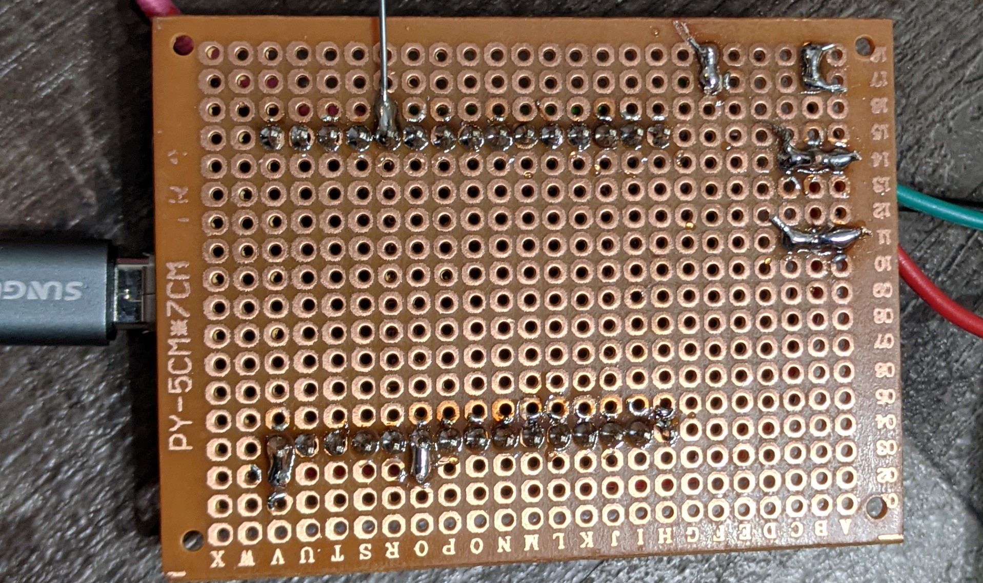
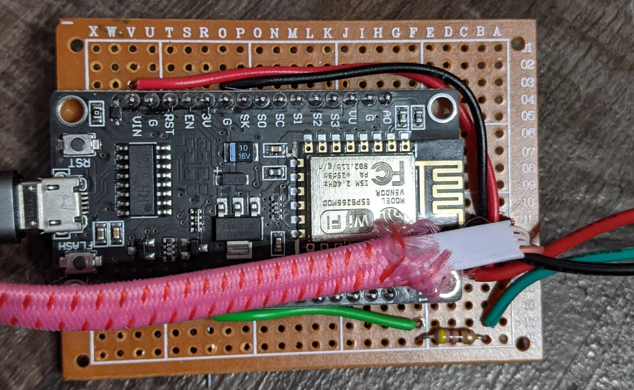
Sadly, of my three ESP-32s, two were broken. I ended up instead using an ESP-8266, since I had several laying around. Annoyingly, the boards I have are so wide it's impossible to breadboard the, so I used perfboard instead.

Having carefully set up the circuit, I flipped the on switch and... nothing happened. It was about 10pm at this point, and I was starting to run out of energy, so I gave up.

Very late that night, I found the problem was the resistor I added--the LED strip has a built-in resistor as well, and apparently the two together were too much. I eventually got the lights to turn on, but too late to finish the project for the day.

 my test pattern looks a little christmas-y
my test pattern looks a little christmas-y
Tagged , , ,

Hack-a-Day, Day 29: ESP32 Microcontroller Documentation

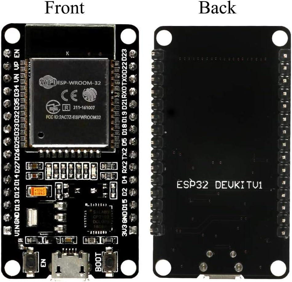
A while back, I was trying to set up a power monitoring system, and I mistakenly bought the wrong ESP dev board. The ones I ended up are sold by some fake-named Chinese manufacturer. They seem pretty fine, much like any other ESP32 dev board, but they have an unusual 30-pin layout.

I tried to add some electronics to my whiteboard hack earlier this month, but got frustrated pretty quickly, failing to program the microcontroller, and with no idea what the pinout was.

Today I decided to take it slower. I'd figure out how to program it, and understand the pins. If I had any time left over, I'd do a project.

First, I got flashing the chip to work. It turns out my main problem from the first time was a bad upload serial rate. I debugged the problem with the help of friendly folks on IRC. Espressif (the ESP32 manufacturer) has helpful troubleshooting instructions, which suggest using the python serial terminal, miniterm. By taking a step at a time, I got the microcontroller working.

Next, I installed and set up platformio, which I had never used before. My experience was that it was pretty good once set up, but a little hard to get started on the command line. Still, I'm happy, and will probably use it again. Platformio has two options--the popular Arduino framework libraries, or the Espressif-provided esp-idf libraries. Based on the small code samples I found, I'll most likely use the Arduino libraries, but some specialty features are just not available on Arduino.

Finally, I set up platformio one last time, with the VS-Code based PlatformIO IDE. Again my experience was pretty good. Sadly, the open-source VS-Code does not show the same set of extensions, and I had to use the binary version. (Aside: Come on, vs-code. Don't call your package and program code. That's a dick move.)

The writeup of how to get your dev environment set up is on github.

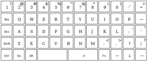
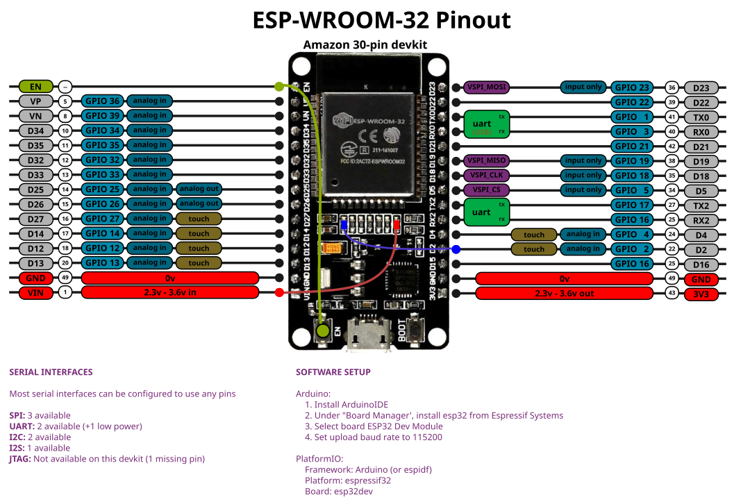
Finally, I made the below pinout diagram with the rest of my night.

 the colors looked better when it was bigger, I swear
the colors looked better when it was bigger, I swear

Happy hacking!

Tagged , ,

Hack-a-Day, Day 22: Homemade PCBs

Today I learned how to make PCBs. I didn’t invent anything here, this is all pretty well known by the PCB-making community, but it’s not well-known to me. So I taught myself a bit!

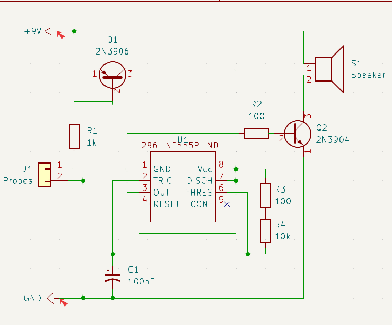
The first part was the design an electronic circuit. I decided I was short on time, so I grabbed an existing schematic.

Next, I downloaded KiCAD, and recreated the circuit there. I found this video tutorial very helpful to learn kicad.

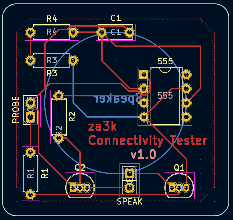
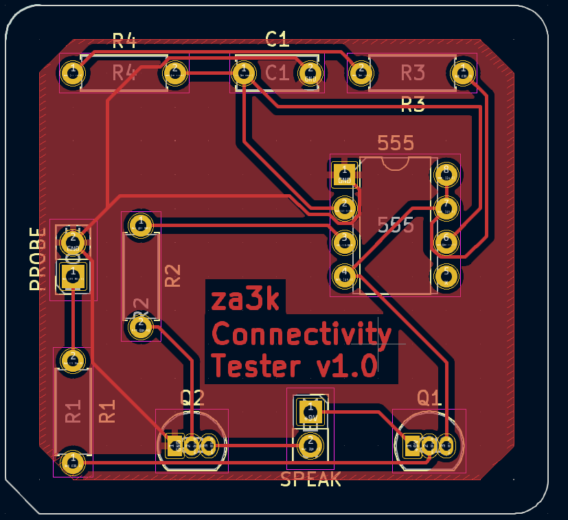
Next, I made the actual PCB layout.

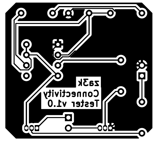
To my surprise, after a little jiggling I got it down to a one-layer design.

That means home-printing would be much easier. No having to line up the two sides carefully.

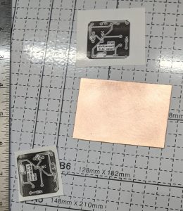
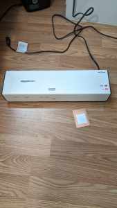
I printed out the image on paper (backwards) on my toner printer, and taped it to the copper-clad PCBs.

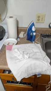
First, I tried laminating it. Almost no ink transferred, and the paper came off easily. Then I tried ironing it, but the paper stick to the iron and not to the PCB. The tape melted on the iron. For both, I dunked them in water after, which is supposed to help loosen the paper.

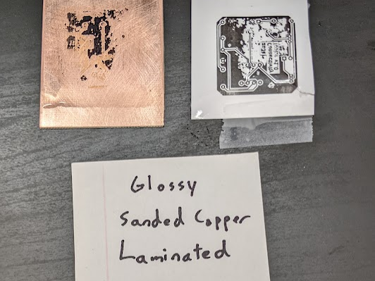
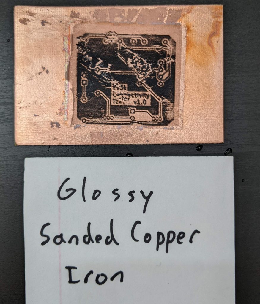
Next, I tried the standard advice–sand the PCBs (I used 320 grit) and use glossy paper. This time, both pieces of paper stuck very well. I was wary about the iron coming off again, so I just left it on place on the highest heat–this worked fine for adhesion, but I had to iron out wrinkles at the end. The laminated piece had lose edges, while the ironed piece was on there totally flat.

I tried peeling off the laminated paper–oops! It peeled back and most of the ink stayed on the paper. I think if I took it off more carefully, it would have worked.

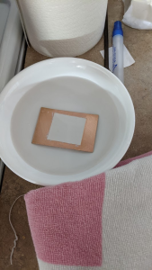
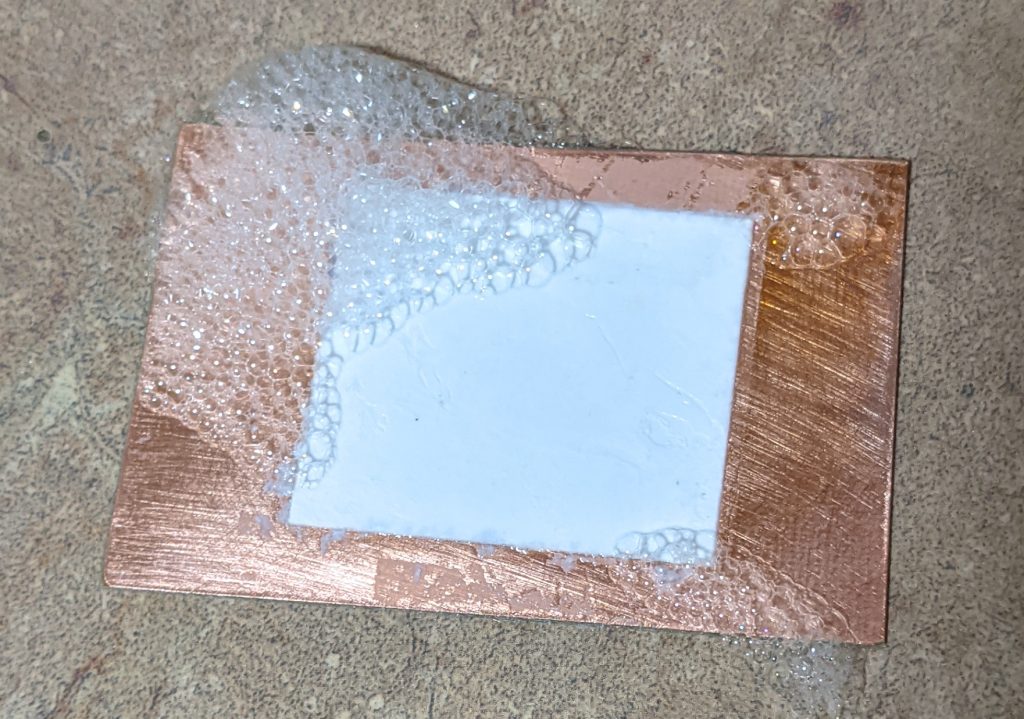
I picked at the ironed paper a bit, but it didn’t budge. I let it sit in dish soap for a while so the paper would fall apart. The first hour didn’t do anything.

Meanwhile, I made an order at PCBWay. It’s still under review.

Edit: after some advice from a friend, I peeled off this paper more aggressively, and scrubbed it off. The ink was fine. It doesn’t look great, but I think this is mostly the wrinkles during transfer. It’s a little blurry, I’ll have to do a third attempt before I try etching.

Tagged , , ,

e-ink “laptop”

I’ve been prototyping an e-ink laptop.

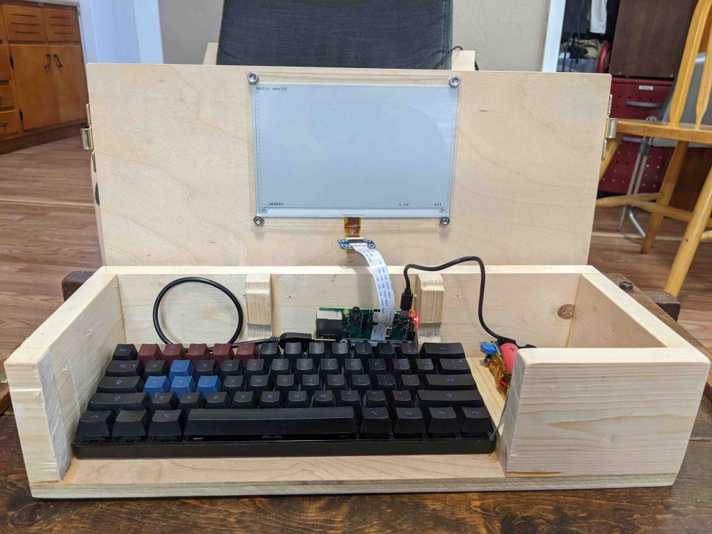
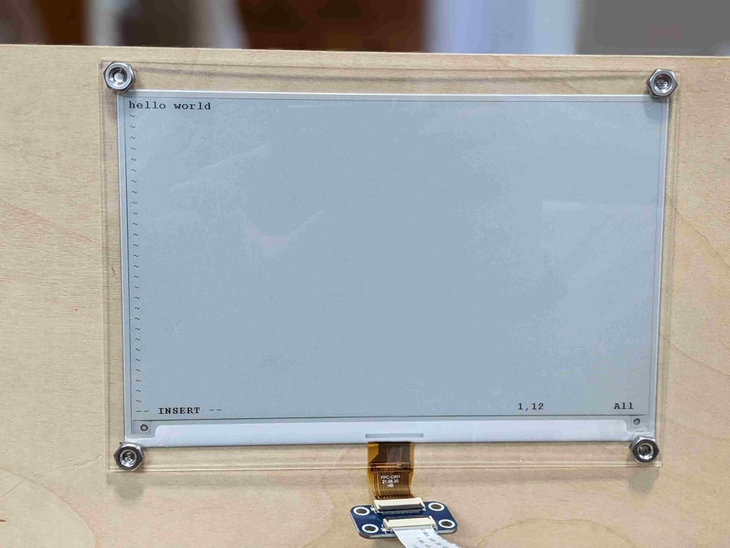
a wooden box with a keyboard inside and an e-ink screen mounted to it
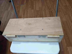
Closed “laptop”
Closed “laptop”

I’m not the first, there have been many other such devices before. I came up with the idea independently, but the specifics are heavily inspired by the Ultimate Writer by NinjaTrappeur in 2018. Similar to him, my use case is typing without distractions, and reading books. E-ink displays are quite slow to update, so I don’t think it can serve as a general purpose computer. Here’s a video of it in action. It operates at one frame per second.

The electronics are not fully done. They need better secured, and I’m going to redo the cabling and power back.

I broke a screen over-tightening a nut. That said, I like this look pretty well! If the lid was thicker, I know how to avoid screws on the other side, too.
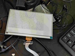
Early screen progress. I got something to display, but not what I wanted.
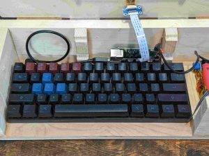
I found a really nice, cheap mechanical keyboard on ebay. The main downside is that it’s heavy–730g. It also consumes heavy amounts of power, even when not in use. I have a nearly identical keyboard that doesn’t, which I’ll use for v2.
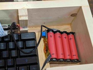
I made my own lithium-ion battery pack. It works well, but it doesn’t quite fit so I’m going to redo it with one less cell. It also needs an on/off switch and a right angle USB cable.
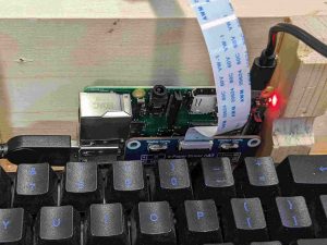
The prototype is powered by a Raspberry Pi 3. The final version will use a microcontroller to save power. The Pi Zero can also be swapped in with no changes, and uses a third of the power. But it’s noticeably slower and takes 30 seconds to boot. For prototyping I’m using the Pi 3 for now.

I’m not the best woodworker, but I’m slowly learning. Here are pictures of case and lid action.

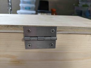
Hinged lid. The screen is on the bottom of the lid.
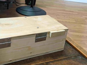
A wooden stop on each side
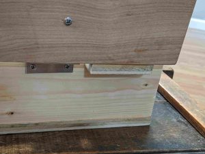
Wooden stop with lid open. It hits the bottom, bringing the lid/screen to a rest at vertical.
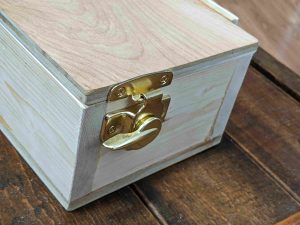
Latches on the side
Latches on the side
Don’t put hinges sideways into plywood. But if you do, drill big pilot holes. Out of six screw, one cracked a little.

On the software end, shout outs to:

  • the creator of the ultimate-writer software, NinjaTrappeur, who has been encouraging (and explained the right way to rewrite the stack, if you wanted to today).
  • Ben Krasnow, who made a video about how to hack partial refresh on an e-ink display.

There’s a few things I’d like to polish still–even as a prototype this isn’t fully done.

  • The raspberry pi and battery pack are currently sitting loose. They need secured, especially since they can fall out the open front.
  • The software has some major problems. It doesn’t support Control-C, etc in linux, a must, and it doesn’t update the screen at boot until you press a key, which would be nice to fix.
  • There’s no power switch. Right now you have to unplug it manually.
  • I’d like to add a carrying handle.
  • I’d like to tuck away the electronics behind a panel. They’re ugly.
  • The wood looks rough in a few places. I want to hide some splintered wood, screw holes, etc.
  • The USB cables have too much stress on them. I need to make a little more room in the wood, and use a right-angled connector in one place.

There’s also no default software, but that’s a feature. A prototype is for figuring out how I want the interface to work, and what I want it to do.

Parts list

  • 7.5 inch e-ink screen from Waveshare (not particularly good) – $60
  • Raspberry Pi 3 (Pi Zero, etc also work with no changes) – $35 (but unavailable)
  • microsd card – $7
  • Plywood and boards, wood glue – $15
  • Plexiglass (to cover screen) – $10
  • Bolts, washers, and nuts to secure it. – $5
  • Circular window latch x2 – $8 (or use $10 smaller version)
  • Hinge x2 – $2
  • Total: $142

Power budget (at 5V):

  • Keyboard: 500mW. Other USB keyboards use zero to within my measurement abilities.
  • Screen: 0-250mW when updating. Hard to measure.
  • Pi 3: 2000mW. I have the wifi chip enabled (the default) but I’m not actively connected to wifi.
  • Pi Zero W: 650mW

A real-life test showed 5-6 hour battery life. Theory says (13Wh/battery * 4 batteries / 2.7 watts)=20 hours battery life. I’m investigating the discrepancy. In theory, swapping for a Pi Zero W and a better keyboard would give 72-hour battery life.

Tagged , , ,