I made my first android app today. It was terrible and I plan to never do it again.
wow! a real app on my phone--well okay, this is an emulator
It took me about three hours of trying to get the sample apps to run before I gave up and made something from scratch. Both involved heavy use of ChatGPT (not my usual flow).
app icon
That said, if you want an app that reminds you how to tie your tie in an easy step-by-step way, you can download the APK from my website, and I believe you should be able to run that on your phone.
I don't know how to easily share Android source code, so I won't.
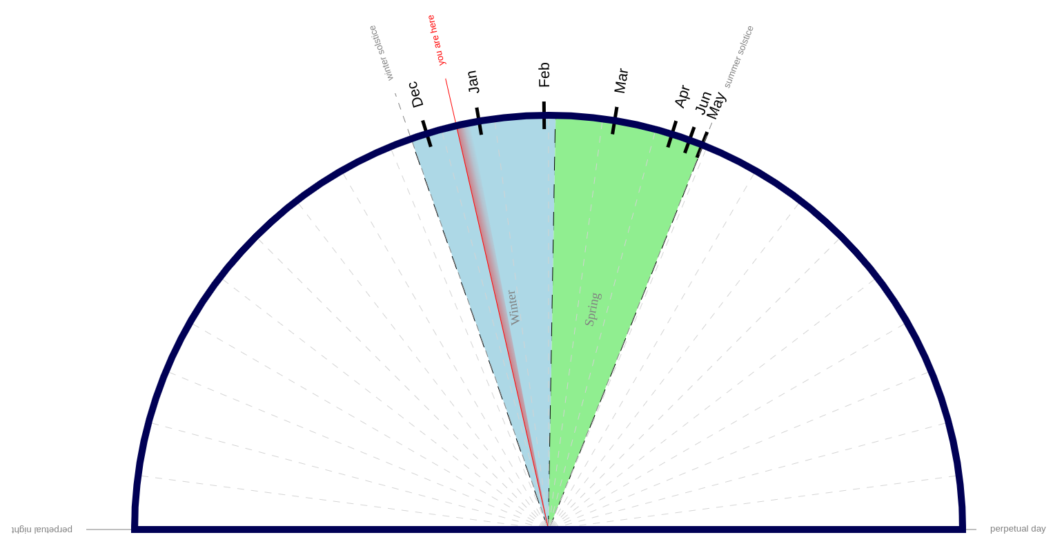
There are 24 hours in a day. This shows you how many of those are daylight. You can use it as a calendar, or you can wistfully watch it, waiting for the sun to come back.
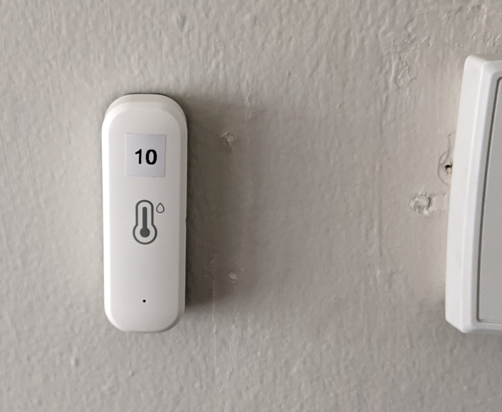
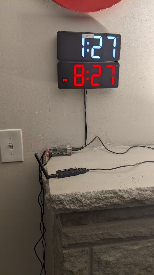
The sensors run on AAA battery, and periodically transmit the temperature on zigbee, a radio protocol in similar frequencies as Wifi. The signals get received by a USB dongle designed to receive and transmit zigbee.
A raspberry pi listens to zigbee using a USB dongle
This is connected to a raspberry pi running zigbee2mqtt. The messages get sent to an mqtt broker via wifi. mqtt is a pub/sub protocol that runs over the internet. Any computer on my LAN can then be notified of temperature updates, by asking the mqtt broker to send them updates.
I wrote a small server which stays on all the time, listening to updates and recording changes to a database. It also generates reports periodically.
I think my database format is mildly interesting, in that it's designed to use a fixed amount of space. Anyone who wants to see the technical details, can check the github repo, specifically this file.
Temperatures can be seen in celsius or fahrenheit online. An example in Fahrenheit is below.
    Current Temperature
    last updated: 2024-11-07 8:34pm

    Sensor                        Temperature  Humidity    Last update
    Outside - Front                51.51°F      69.86%     1 minutes ago
    Outside - Back                 64.26°F      99.99%     22 hours, 49 min ago
    Upstairs - Dining Room         69.67°F      53.24%     0 minutes ago
    Upstairs - Bedroom - Za3k      71.35°F      60.15%     21 minutes ago
    Upstairs - Bedroom - Master    68.90°F      58.11%     4 minutes ago
    Upstairs - Kitchen             71.20°F      50.50%     6 minutes ago
    Upstairs - Garage              65.55°F      60.65%     2 minutes ago
    Basement - HVAC/Server         68.02°F      51.27%     3 minutes ago
    Basement - Workshop            67.10°F      52.91%     14 minutes ago

    -------------

    Hourly Temperature
    last updated: 2024-11-07 8:34pm

                    outside    inside
    2024-11-07  8am    54.49°F    69.44°F
    2024-11-07  9am    53.81°F    69.04°F
    [...]
    2024-11-07  6pm    56.11°F    69.86°F
    2024-11-07  7pm    53.53°F    69.65°F

    -------------

    Historical highs and lows
    last updated: 2024-11-07 8:34pm

                outside             inside
    2024-11-07    51.51 -  64.15°F    67.06 -  81.54°F
    2024-11-06    61.21 -  71.24°F    68.36 -  81.18°F
    [...]
    2024-10-10    49.39 -  60.89°F    67.59 -  77.49°F

    -------------

    Code: https://github.com/za3k/temp-monitor
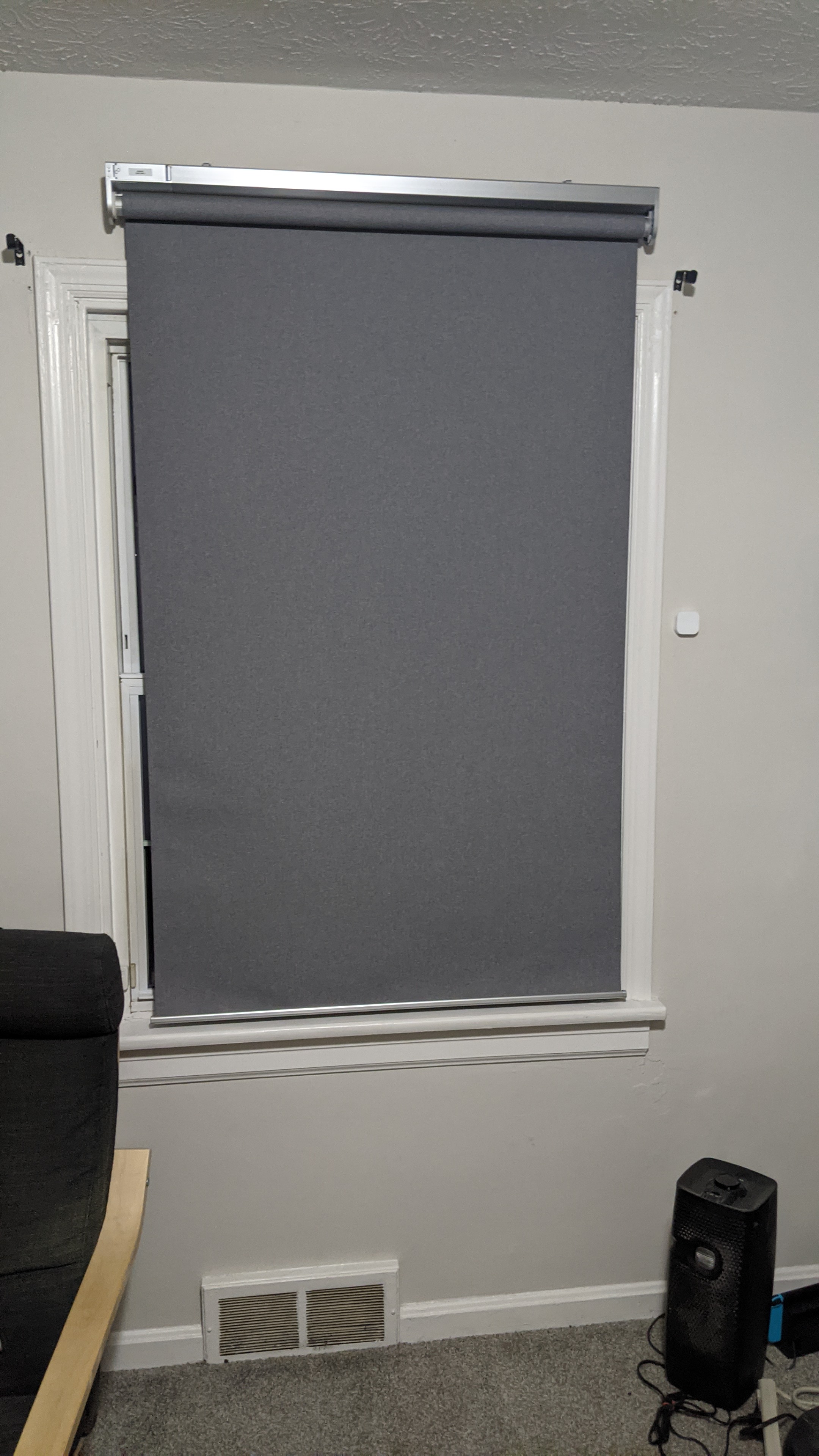
Having tested out zigbee and mqtt, I felt ready for my actual use case -- curtains. I live across the street from a major parking lot, and they have floodlights on all night. To sleep, I need blackout curtains. The problem is, it's pretty hard to wake up with blackout curtains drawn.
My solution was to get some smart curtains, and have them automatically go down at the end of the day, and go up in the morning.
Smart curtains from IKEA
This worked fine, after I got the curtains set up. I've completely forgotten about them, which is exactly how I like my home automation--I want to never think about it. For more about how to set up IKEA smart curtains, see my notes. It comes with 6 manuals.
blinds controls my blinds via the computer, and mqtt2mqtt allows my IKEA remote to control them too. cron and heliocron automatically open and close the curtains on a timer.
I worked on monitoring power usage via my circuit breaker with current transformers and the circuitsetup ESP32 energy meter but it's currently stalled. The main problem is that I can't fit the CTs into my circuit breaker. If I get it working, I'll post an update.
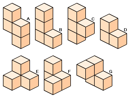
The Soma Cube is a 3D, tetris-like puzzle -- picture credit 2ndlook.nl
Today I tried to design a laser-cut set of Soma cube pieces. The pieces (shown above) are (conceptually, and sometimes actually) made of 3D blocks glued together.
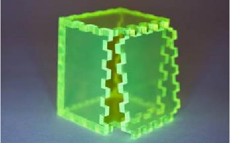
I've seen a particular style of joinery for acryllic, called finger joints. Those looked easy to cut and easy to put together (if hard to design).
Acrylic box made with finger joints -- photo credit txoof
I wrote a python script that takes a description of a piece, like this:
Piece E
xx x-
x- --
-- --
And draws all the flat faces I need to cut.
Flat faces for the soma cube
I was already running far behind, time-wise. I ran out of time before I could get the joinery working. Honestly, I don't think I'm very close, either.
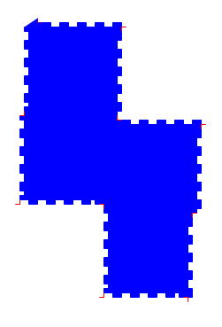
Finger joins drawn incorrectly with turtle graphics
How to do a three-piece corner join was especially confusing me.
Lately I’ve been messing about in Godot, a framework for making video games (similar to Unity).
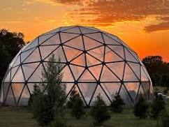
I wanted to make a 3D game. In my game, you live in a geodesic dome, and can’t go outside, because mumble mumble mumble poisonous atmosphere?.
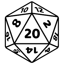
A geodesic dome, I learned, is related to the icosahedron, or d20 from RPGs.
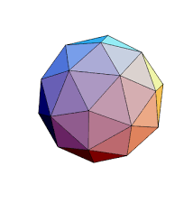
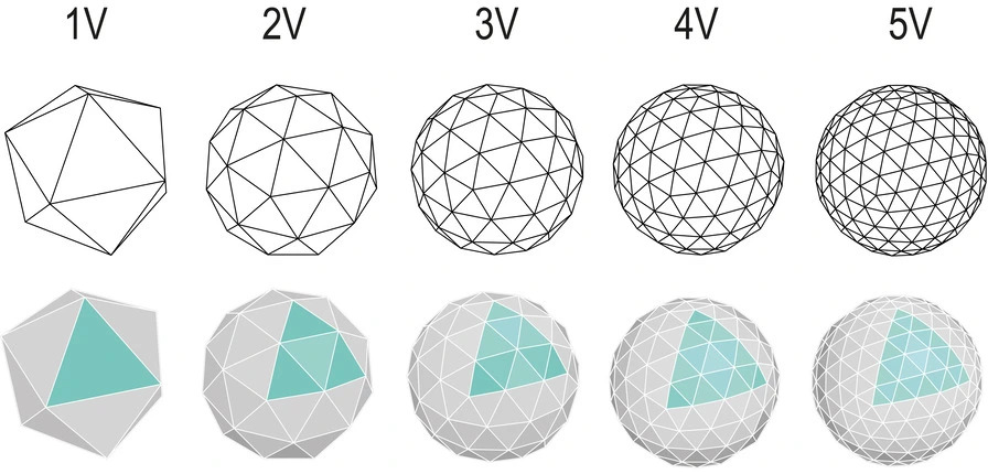
A simple dome is the top half of the icosahedron. As they get more complex, you divide each triangle into more and more smaller triangles.
Icosahedron getting more and more detailed. Geodesic domes are the top half of each sphere.
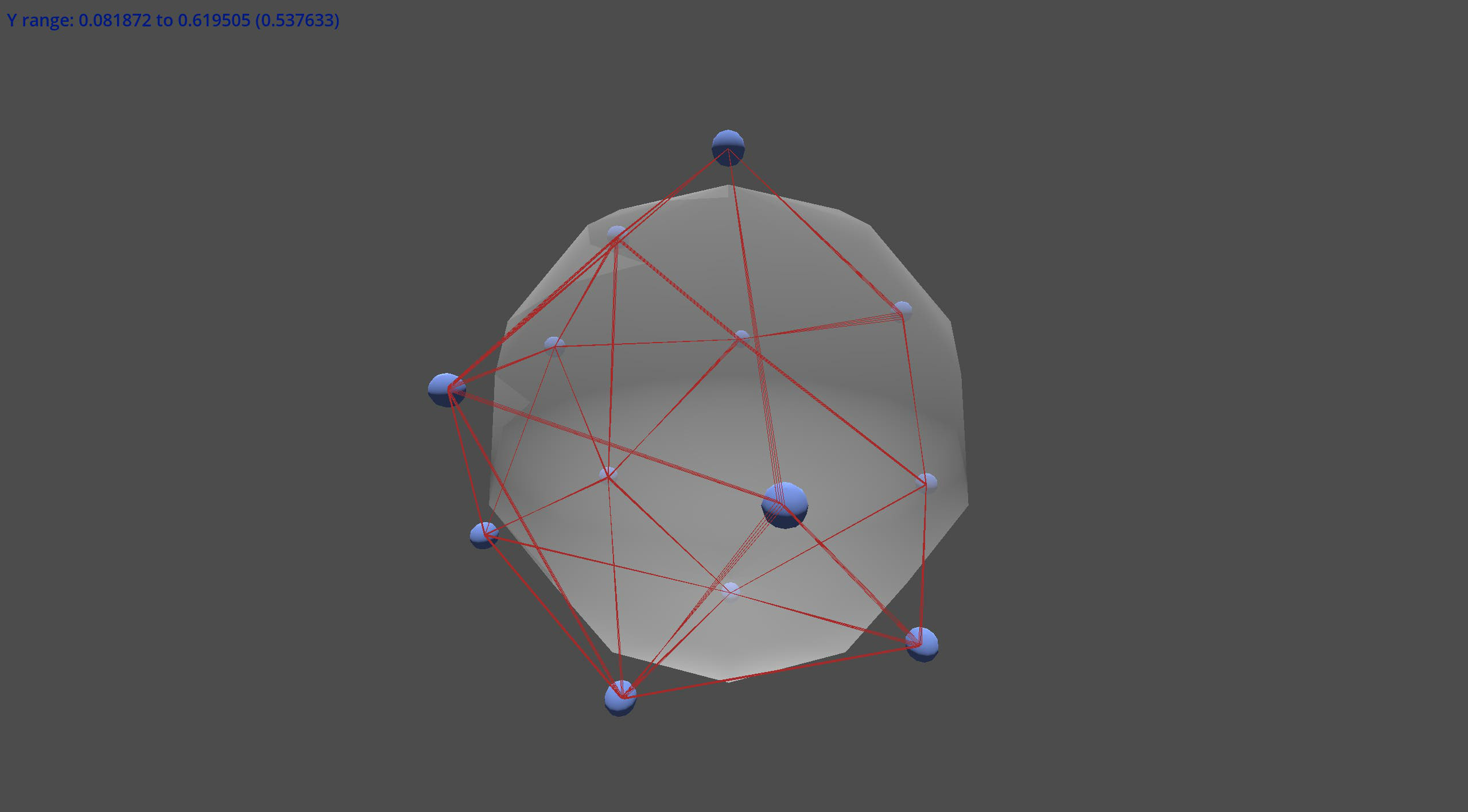
So to make a nice geodesic dome, we could find one (I failed), make one in Blender (too hard), or use some math to generate one in Godot. And to do that math, we need to know the list of 20 icosahedron faces. Which basically just needs the list of the 12 vertices!
Now, obviously you could look up the vertices, but I thought of a more fun way. Let’s put 12 points on a sphere, make them all repel each other (think magnetically, I guess), and see where on the sphere they slide to. Maybe they will all be spaced out evenly in the right places. Well, here’s what it looks like:
So… kinda? It was certainly entertaining.
By the way, the correct coordinates for the vertices of an icosahedron inside a unit sphere are:
the top at (0, 1, 0)
the bottom at (0, -1, 0)
10 equally spaced points around a circle. they alternate going up and down below the center line.
(±1/√5, sin(angle), cos(angle)) [projected onto the sphere]
When you click an email address, it automatically opens in your email client. But I don’t have an email client, I use webmail. I wrote a custom handler for Linux.
First write a program to open mailto links. Mailto links look like “mailto:me@mail.com” or maybe even “mailto:me@mail.com?subject=mysubject&body=mybody“. Test it by hand on a few links. Mine (mailto-opener) composes a new message using my webmail.
Next, write a desktop file for the opener. Here’s one:
#/usr/local/share/applications/mailto-opener.desktop
[Desktop Entry]
Type=Application
Name=mailto: link opener (github.com/za3k/short-programs)

# The executable of the application, possibly with arguments.
Exec=/home/zachary/.projects/short-programs/mailto-opener %u
Note the %u in the Exec= line. That’s required.
Now update your system mimetype database. On my Arch Linux install, I run
Finally, restart your browser. Really. Firefox and Chromium/Chrome both cache mimetype openers.
A related opener I added recently was for magnet links, such as are popularly used for bittorrent.
~ $ cat /usr/local/share/applications/transmission-remote.desktop
[Desktop Entry]
Type=Application
Name=transmission-remote magnet link opener
Exec=transmission-remote <TRANSMISSION INSTANCE> -a
transmission-remote is the name of a command-line Linux program. It connects to an instance of Tranmission (a popular torrent client) running on another machine.
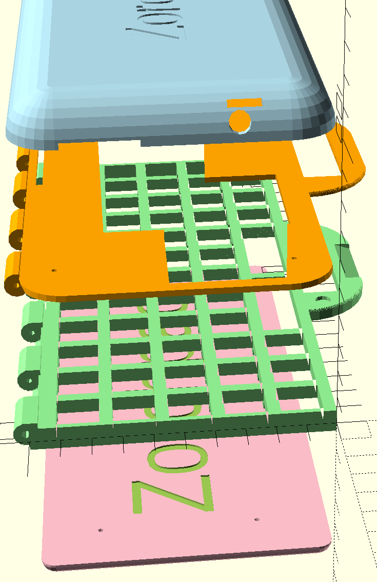
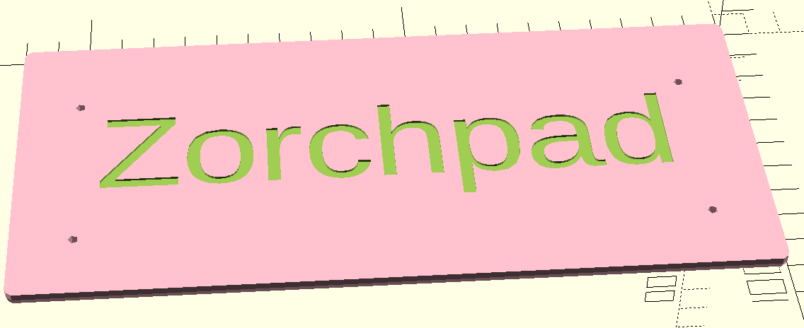
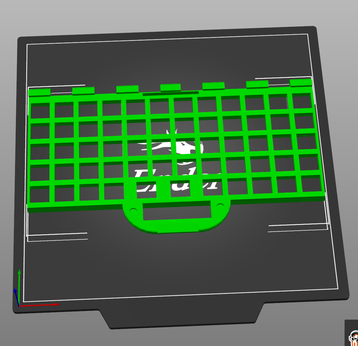
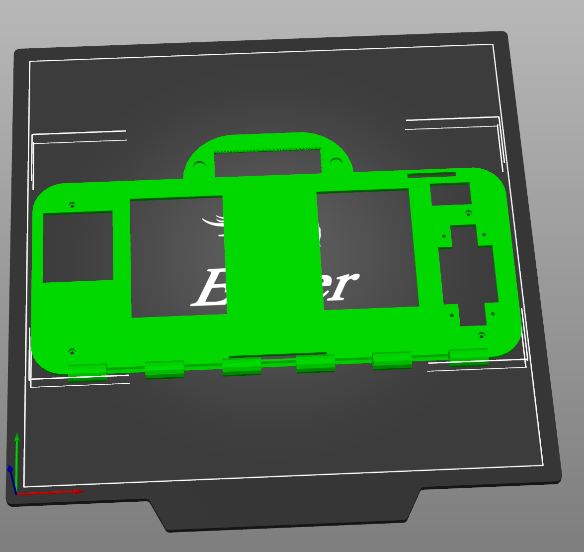
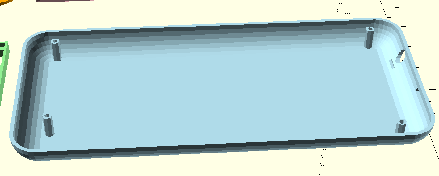
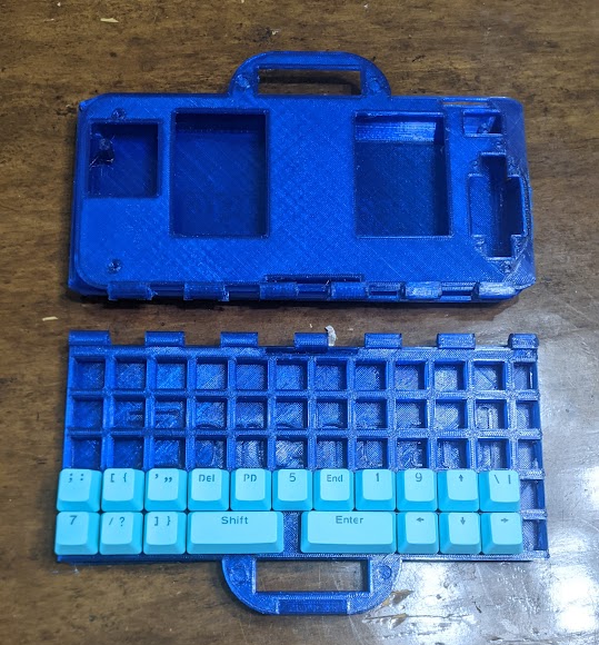
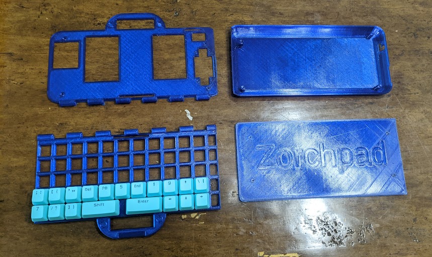
I’ve been designing a keyboard and case for the zorchpad.
There are four pieces in the first iteration.
A top bottom base, to enclose the keyboard electronics.
A keyboard plate. The keys fit into the holes here. You type on the top, electronics go in the bottom.
A top plate. You see the screens, and switches through the cutouts. Otherwise, it keeps the behind-the-scenes wiring out of sight.
And finally, the top piece.
Here are the pieces in correct position. In the top will be the screens and battery. The bottom is a keyboard you type on. The whole things is meant to fold on a hinge, much like a laptop.
The same pieces, spread out.
There were many, many problems with the first design and the first print. I’ll talk about them (and my fixes) in my next post.